|
|
|
Categories
|
|
Information
|
|
Featured Product
|
|
|
 |
|
|
There are currently no product reviews.
 ;
Hr, klasse , good manual, verry fast on my e-mail, very usefull manual. rgds; ahm zeegers
;
I received the owners manual complete download. Wow did it help me. So glad for your website. Can you include an ownersmanual for people lol!
Thanks, sure I will be back
;
fast response great copy easy to download quick to correct mistakes
;
This manual provided the necessary information to properly use the C-3 deck. The manual was an excellent reproduction and very clear.
;
Product was very good. Received quickly and complete
TH-A9R Removing the power amplifier board (B) (See Figs.9 and 11)
Prior to performing the following procedure, remove the heat sink cover, the amplifier assembly, the amplifier cover, the preamplifier board, the power supply & SP terminal board, the main amplifier board and power amplifier board (A). 1. Remove the four screws L attaching the power
Power amplifier board (B) Hooks Joint c
CN106
amplifier board (B) to the heat sink. 2. Release the four joint hooks c bent and attached to the outside of the power amplifier board (B). 3. Move the power amplifier board (B) in the direction of the arrow to release joint d and remove the power amplifier board (B) from the bracket (B).
CN105 Joint d Braket (B) Joint c
Fig.11
Main amplifier board
Removing the power transformer (See Figs.12 and 13)
Prior to performing the following procedure, remove the heat sink cover, the amplifier assembly, the amplifier cover, the preamplifier board, the power supply & SP terminal board, the main amplifier board, the power amplifier board (A) and power amplifier board (B). 1. Disconnect the harness from connector CN104 on the main amplifier board. 2. Disconnect the wire from connector CN107 on the power supply & SP terminal board. 3. Remove the four screws M attaching the power transformer.
Power supply & SP terminal board
M
CN104 CN108 CN107 Power transformer
N
Cord stopper N braket AC cord
M M
Fig.12
Removing the AC power cord (See Fig.12)
Prior to performing the following procedure, remove the heat sink cover, the amplifier assembly, the amplifier cover, the preamplifier board, the power supply & SP terminal board, the main amplidier board, the power amplifier board (A), the power amplifier board (B) and power transformer. 1. Disconnect the wire from connector CN108 on the power supply & SP terminal board.
CN110 Preamplifier board CN101
Power supply & SP terminal board
Main amplifier board CN111
2. Remove the two screws N attaching the AC power cord.
CN108 CN107
Fig.13 1-17
 $4.99 TH-A9 JVC
Circuit Diagrams Set of circuit diagrams. The diagrams will be provided as PDF file. The file will be delivered after… 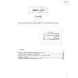 $4.99 TH-A9 JVC
Parts Catalog Parts Catalog only. It's available in PDF format. Useful, if Your equipment is broken and You need t… 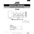 $4.99 THA9 JVC
Service Manual Complete service manual in digital format (PDF File). Service manuals usually contains circuit diagr…
|
|
|
> |
|