|
|
|
Categories
|
|
Information
|
|
Featured Product
|
|
|
 |
|
|
There are currently no product reviews.
 ;
exactly as they say. Within 24 hours the link to the pages and offcourse it was the right service manual. Super and thanks
 ;
The manual was exact the thing that was promised. My old car stereo is working again thanks to the information supplied.
;
I PURHASED THIS PRODUCT BECAUSE I WAS HAVING PROBLEMS WITH MY CDR20 HARMAN KARDON RECORDER. WHICH I PURCHASED NEW 12 YEARS AGO. AFTER REVIEWING THE MANUAL, I WAS ABLE TO ADJUST THE TENSIONER IN THE SYSTEM. WORKS LIKE A CHAMP!.
SAVED ME AT LEAST 100.00 WHICH WAS WHAT A SERVICE REPAIR STATION WANTED. GREAT MANUAL EASY TO READ. SPECIALLY AFTER I PRINTED THE PAGES WHICH DEALT WITH MY RECORDER. THANKS A LOT!!!!!!!!
;
You can fully trust on this one!
All the schematics are very crear an in one piece per page
;
I have never bought a service manual which is as competely readable as this althogh it was a scanned pdf. Thank you for this succesful manual also cheaper than other sites.
TH-A9R Removing the power amplifier board (B) (See Figs.9 and 11)
Prior to performing the following procedure, remove the heat sink cover, the amplifier assembly, the amplifier cover, the preamplifier board, the power supply & SP terminal board, the main amplifier board and power amplifier board (A). 1. Remove the four screws L attaching the power
Power amplifier board (B) Hooks Joint c
CN106
amplifier board (B) to the heat sink. 2. Release the four joint hooks c bent and attached to the outside of the power amplifier board (B). 3. Move the power amplifier board (B) in the direction of the arrow to release joint d and remove the power amplifier board (B) from the bracket (B).
CN105 Joint d Braket (B) Joint c
Fig.11
Main amplifier board
Removing the power transformer (See Figs.12 and 13)
Prior to performing the following procedure, remove the heat sink cover, the amplifier assembly, the amplifier cover, the preamplifier board, the power supply & SP terminal board, the main amplifier board, the power amplifier board (A) and power amplifier board (B). 1. Disconnect the harness from connector CN104 on the main amplifier board. 2. Disconnect the wire from connector CN107 on the power supply & SP terminal board. 3. Remove the four screws M attaching the power transformer.
Power supply & SP terminal board
M
CN104 CN108 CN107 Power transformer
N
Cord stopper N braket AC cord
M M
Fig.12
Removing the AC power cord (See Fig.12)
Prior to performing the following procedure, remove the heat sink cover, the amplifier assembly, the amplifier cover, the preamplifier board, the power supply & SP terminal board, the main amplidier board, the power amplifier board (A), the power amplifier board (B) and power transformer. 1. Disconnect the wire from connector CN108 on the power supply & SP terminal board.
CN110 Preamplifier board CN101
Power supply & SP terminal board
Main amplifier board CN111
2. Remove the two screws N attaching the AC power cord.
CN108 CN107
Fig.13 1-17
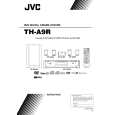 $4.99 THA9R JVC
Owner's Manual Complete owner's manual in digital format. The manual will be available for download as PDF file aft…
|
|
|
> |
|