|
|
|
Categories
|
|
Information
|
|
Featured Product
|
|
|
 |
|
|
There are currently no product reviews.
 ;
The service manual is really great - thanks to it I was able to install the laser unit and thus "save" my CD-player, which seemed to be impossible before I had the manual.
;
Downloaded the Service manual OK of the Technics Piano and have now repaired it and its going fine. Excellant; thank you for the fine servce. A.M
 ;
This site is working fine! Did buy a manual for SX-EX25L and after a while I could download it and fix the problem. Nice and easy!
;
Complete manual as pdf-file in very good quality. Very helpful and fast availability.
;
Complete service manual in very good scanning quality with all schematic and PWB graphics as well as assembly & maintenance instructions. A slight drawback is that the rastering of the PWB graphics sometimes makes it a bit difficult to follow fine traces, but no showstopper.
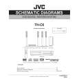
3.3.7 Removing the DVD pickup (See Figs.12 to 14) � Remove the tray assemblies, DVD servo board and DVD traverse mechanism assembly. (1) From the top side of the DVD traverse mechanism assembly, release the lock of the connector on the DVD pickup and disconnect the card wire in the direction of the arrow. (See Fig.12.) (2) Turn the screw shaft gear in the direction of the arrow 1 to move the DVD pickup in the direction of the arrow 2. (See Fig.12.) (3) Remove the screw G attaching the feed bracket and remove the feed bracket from the sections k. (See Fig.12.) (4) Release the claw m of the thrust spring in the direction of the arrow and remove the thrust spring. (See Fig.12.) (5) Remove the guide shaft from the sections (n, p) on the C.TM chassis. (See Fig.13.) (6) Remove the section q of the DVD pickup. (See Fig.13.) (7) Remove the two screws H attaching the rack arm spring and rack arm. (See Fig.14.) (8) Pull the guide shaft from the DVD pickup in the direction of the arrow. (See Fig.14.) 3.3.8 Attaching the DVD pickup (See Figs.12 to 14) (1) Attach the guide shaft to the DVD pickup and attach the rack arm spring and rack arm with the screws H. (See Fig.14.) (2) Attach the section q of the DVD pickup to the C.TM chassis first and attach the guide shaft to the sections (n, p). (See Fig.13.) Reference: When attaching the guide shaft to the section p, attach it under the rod spring. (See Fig.13.) (3) Attach the thrust spring and feed bracket with the screw G. (See Fig.12.) (4) Turn the screw shaft gear in the direction of the arrow 1 to move the DVD pickup in the direction of the arrow 2. (See Fig.15.) (5) Connect the card wire to the connector on the DVD pickup. (See Fig.15.)
DVD traverse mechanism assembly Thrust spring Connector
Feed bracket
2
G
1
k Screw shaft gear DVD pickup Thrust spring
m
Fig.12
DVD pickup
q
p Rod spring Guide shaft C.TM chassis
Fig.13
n
1-20 (No.MB382)
 $4.99 TH-C6 JVC
Circuit Diagrams Set of circuit diagrams. The diagrams will be provided as PDF file. The file will be delivered after…  $4.99 TH-C6 JVC
Parts Catalog Parts Catalog only. It's available in PDF format. Useful, if Your equipment is broken and You need t…
|
|
|
> |
|


