|
|
|
Categories
|
|
Information
|
|
Featured Product
|
|
|
 |
|
|
There are currently no product reviews.
 ;
Very helpful and complete manual. Maybe only one negative is schematics have sometimes unreadable name of the parts. But it's not a big problem.
 ;
Excellent high quality schematics brought my old Heidelberg back to life. Fast download at a reasonable price. Thanks.
;
This document is just what I was looking for, it´s very useful, it contains adjustment procedures for the final stage of the power amp and also
has a complete wiring diagram and description of the main semiconductors used in the design.
;
Dear Sirs,
Thank you for the fast support, the manual does provide all necessary information to repair the radio. All schematics are in a good quality for reading.
The manual fits 100% to my requirements as a technican.
Kind regards Thomas
;
the big video recorder format s-vhs many features delicate in loading system of the cassette. Such machines are no longer manufactured, it would be too expensive.
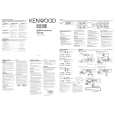
TH-K2AT/K2E/K2ET
DISASSEMBLY FOR REPAIR
Soldering the antenna terminal
1. With the shield cover removed from the antenna terminal section, install two screws on the PC board and bring the PC board into contact with the chassis (z). 2. Solder the antenna terminal with a soldering iron (x). 4. Apply the tips of soldering irons to all the four pins of the final FET at the same time (c), heat them sufficiently, and remove the final FET (v). (Two persons should be required to do this.)
x z
v
c
5. Remove all PC boards from the chassis. 6. Confirm that there is no space between the radiation plate installed on the foil side of the TX-RX PC board (TX-RX unit A/3) and the PC board (b). If there is any space between the radiation plate and PC board, eliminate it by applying the tip of the soldering iron to the radiation plate. 3. Remove the two screws installed in step 1 above, and install the two screws again on the PC board together with the shield cover (c).
b
Radiation plate
c
TX-RX PC board 7. Apply the tip of the soldering iron to the installation side of the radiation plate of the TX-RX PC board, put a little amount of solder to the radiation plate that is seen through a square hole in the final FET installation section and melt the solder (n). 8. When the solder in step 7 is melted, place the final FET on the PC board by aligning it with the silk of the final FET installation section of the PC board (m).
Replacing the final FET (Q12)
1. Remove the two screws holding the shield cover of the final FET section (z). 2. Remove solder from the shield cover completely with a solder absorber. (E and E3 types only) 3. Remove the shield cover (x).
m n
z x
9. Release the soldering iron and confirm that the final FET and radiation plate have been soldered. 10. Solder the four pins of the final FET with the soldering iron. 11. Install all the PC boards. 12. Reinstall the shield cover removed in step 3 above in its original position and install two screws. 13. Solder the shield cover to the PC board. (E and E3 types only) 14. Install the chassis on the case assembly and assemble them. 15. Readjust transmission power. Note: Since the FET is sensitive to static electricity, always wear a grounding band. Use a highly insulated ceramic heater solder iron.
3
|
|
|
> |
|