|
|
|
Categories
|
|
Information
|
|
Featured Product
|
|
|
 |
|
|
There are currently no product reviews.
 ;
This site is working fine! Did buy a manual for SX-EX25L and after a while I could download it and fix the problem. Nice and easy!
 ;
Complete manual as pdf-file in very good quality. Very helpful and fast availability.
;
Complete service manual in very good scanning quality with all schematic and PWB graphics as well as assembly & maintenance instructions. A slight drawback is that the rastering of the PWB graphics sometimes makes it a bit difficult to follow fine traces, but no showstopper.
;
Purchased the manual that I was looking for at a great price and could download it easily.. Great service experience and for future purchases I plan to use the site. Thank you very much
;
Service manual in good quality, it was very helpful to me. Perfect service, I am very satisfied.
Jochen Kelm
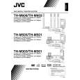
3.4.2 Removing the rear panel (See Figs.4 and 5) � Prior to performing the following procedures, remove the amplifier assembly. (1) From the back side of the amplifier assembly, remove the four screws C, two screws D and screw E attaching the rear panel. (See Fig.4) (2) From the top side of the amplifier assembly, take out the rear panel with fan motor, and disconnect the wire from the connector CN371 on the mother board. (See Fig.5) 3.4.3 Removing the fan motor (See Figs.4 and 5) � Prior to performing the following procedures, remove the amplifier assembly. (1) From the back side of the rear panel, remove the two screws F attaching the fan motor. (See Fig.4) (2) From the top side of the amplifier assembly, take out the fan motor and disconnect the wire from the connector CN371 on the mother board. (See Fig.5)
E
F
C C D
Fig.4
Rear panel
Mother board
CN371
3.4.4 Removing the heat sink BKT (See Figs.6 and 7) � Prior to performing the following procedures, remove the amplifier assembly and rear panel. (1) From the left side of the amplifier assembly, remove the wires from the wire clamp on the heat sink BKT. (See Fig.6) (2) From the left side of the amplifier assembly, remove the four screws G attaching the heat sink BKT. (See Fig.7) (3) Take out the two heat sink BKT. Reference: After attaching the heat sink BKT, bundle the wire by the wire clamp. (See Fig.6)
Fan motor
Fig.5
Amplifer assembly
Wire clamp
Wire
Heat sink BKT Fig.6
Wire
Mother board
G
Fig.7
Mother board
G
1-28 (No.MB288)
 $4.99 TH-M303 JVC
Owner's Manual Complete owner's manual in digital format. The manual will be available for download as PDF file aft… 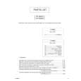 $4.99 TH-M303 JVC
Parts Catalog Parts Catalog only. It's available in PDF format. Useful, if Your equipment is broken and You need t…
|
|
|
> |
|