|
|
|
Categories
|
|
Information
|
|
Featured Product
|
|
|
 |
|
|
There are currently no product reviews.
 ;
This manual was very clear and complete, the prices can't be beat, great to have older manuals available!
 ;
Doubted for buy this manual as it is my first order here and at not have cover image, I assumed would haven't. However, within 24 hs, already possessed the link to download it. The manual are scanned correctly and have all what is needed. Includes adjustments and diagrams of all circuits. Very satisfied.
;
Really good quality, аll readable.! Wonderful work shop. I recommend to all!
;
Good quality service manual.The scheme is on A3 format and very readable.Thank you
;
Very good service-manual with clear electrical diagrams. Thanks you.
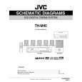
3.1.9 Removing the connect board (See Fig.14) � Remove the metal cover. � Remove the front panel assembly. (1) From the inside of the front panel assembly, disconnect the card wire from the connector CN561 on the connect board. (2) Remove the screw V attaching the support board. (3) Take out the connect board. 3.1.10 Removing the phone jack board (See Fig.14) � Remove the metal cover. � Remove the front panel assembly. (1) From the inside of the front panel assembly, remove the two screws W attaching the phone jack board. (2) Take out the phone jack board.
Phone jack board
W
CN561
Connect board
W V
Card wire
Support board
Fig.14
3.1.11 Removing the operation board (See Fig.15) � Remove the metal cover. � Remove the front panel assembly. � Remove the support board. (1) Remove the two screws X attaching the operation board. (2) Take out the operation board together the Button(top). Reference: Remove the Button(top) from the front board as required. 3.1.12 Removing the front board (See Figs.15 and 16) � Remove the metal cover. � Remove the front panel assembly. � Remove the connect board. � Remove the operation board. (1) From the front side of the front panel assembly, pull out the volume knob. (See Fig.16.) (2) Remove the screw Y attaching the front board. (See Fig.16.) (3) From the inside of the front panel assembly, remove the eight screws Z attaching the front board. (See Fig.15.) (4) Take out the front board while releasing the claws e in the direction of the arrow. (See Fig.15.)
Front board
X Z
Operation board Button(top)
Z
Claws e
Fig.15
Z
Front panel assembly
Y
Volme knob
Fig.16
(No.MB033)1-13
 $4.99 TH-M45 JVC
Circuit Diagrams Set of circuit diagrams. The diagrams will be provided as PDF file. The file will be delivered after… 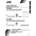 $4.99 TH-M45 JVC
Owner's Manual Complete owner's manual in digital format. The manual will be available for download as PDF file aft… 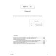 $4.99 TH-M45 JVC
Parts Catalog Parts Catalog only. It's available in PDF format. Useful, if Your equipment is broken and You need t…
|
|
|
> |
|