|
|
|
Categories
|
|
Information
|
|
Featured Product
|
|
|
 |
|
|
There are currently no product reviews.
 ;
+++ Is is fine, that was what i looking for. Thanks! +++
;
A very good complete archive, i am very satisfied for document.
 ;
The Service Manual received was helpful. The electronic information is exactly what I needed.
;
The Manual was perfect.
The deliverie was perfect.
Thanks
;
Found website easy to use and manual very clear. First class service
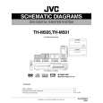
3.3.7 Removing the DVD pickup (See Figs.12 to 14) � Prior to performing the following procedures, remove the tray assemblies and DVD traverse mechanism assembly. (1) From the topside of the DVD traverse mechanism assembly, solder the short-circuit points i on the DVD pick up. (See Fig.12) Caution: Solder the short-circuit points i on the DVD pickup before disconnecting the flexible wire extending from the DVD pickup. If you do not follow this instruction, the DVD pickup may be damaged. (2) Disconnect the flexible wire from the connector on the DVD pickup. (See Fig.12) (3) Turn the screw shaft gear in the direction of the arrow 1 to move the DVD pickup in the direction of the arrow 2. (See Fig.12) Remove the screw G attaching the gear holder. (See Fig.12) Remove the screw H attaching the SS adj. spring. (See Fig.12) Move the DVD pickup in the direction of the arrow and remove the screw shaft from the section j on the screw shaft holder. (See Fig.13) Remove the section k of the DVD pickup from the guide shaft. (See Fig.13) Remove the two screws J attaching the rack arm to the DVD pickup. (See Fig.14) Pull the screw shaft from the DVD pickup in the direction of the arrow. (See Fig.14)
Short circuit points i DVD traverse mechanism assembly Connector Flexible wire
2 Screw shaft gear 1 SS adj. spring
(4) (5) (6)
G
Gear holder DVD pickup Section k
H
DVD pickup Fig.12 Guide shaft
(7) (8) (9)
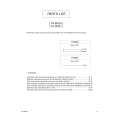
3.3.8 Attaching the DVD pickup (See Figs.12 to 14) (1) Attach the screw shaft to the DVD pickup and attach the rack arm with the screws J. (See Fig.14) Reference: After attaching the screw shaft to the DVD pickup, attach the screw shaft collar to the screw shaft. (See Fig.14) Attach the section k of the DVD pickup to the guide shaft first and attach the screw shaft to the section j on the screw shaft holder. (See Fig.14) Attach the SS adj. spring and gear holder with the screws G and H. (See Fig.12) Turn the screw shaft gear to move the DVD pickup toward the left. (See Fig.12) Connect the flexible wire to the connector on the DVD pickup. (See Fig.12)
Section j
(2)
Screw shaft
(3) (4) (5)
Screw shaft holder Fig.13 DVD pickup
Caution: Unsolder the solders from the short-circuit points i after connecting the flexible wire.
Rack arm Screw shaft collar
J
Screw shaft
Fig.14
(No.MB192)1-17
 $4.99 TH-M505 JVC
Parts Catalog Parts Catalog only. It's available in PDF format. Useful, if Your equipment is broken and You need t…
|
|
|
> |
|