|
|
|
Categories
|
|
Information
|
|
Featured Product
|
|
|
 |
|
|
There are currently no product reviews.
 ;
I will definitely be back for more information when I need it.
;
The service manual when downloaded and printed out was clear and easy to read. I would have liked to have been able to enlarge some details, but this was not possible as the file permissions did not allow this. The service was very good. The time taken from placing my order to downloading the document was only a few minutes.
 ;
The manual is useful for trouble shooting for an old instrument. It saved money,and let me enjoy DIY.
;
Perfect source of information for replacing the HDD and performing general diagnostics.
;
Perfect source of information for replacing the HDD and performing general diagnostics.
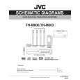
3.4.2 Removing the rear panel (See Figs.3 and 4) � Prior to performing the following procedure, remove the amplifier assembly. (1) From the back side of the amplifier assembly, remove the five screws C, screw D and screw E attaching the rear panel. (See Fig.4) (2) From the top side of the amplifier assembly, take out the rear panel with fan motor, and disconnect the wire from the connector CN202 on the amplifier board. (See Fig.3) 3.4.3 Removing the fan motor (See Fig.4) � Prior to performing the following procedures, remove the amplifier assembly and rear panel. (1) From the front side of the rear panel, remove the four screws F attaching the fan motor. (2) Take out the fan motor.
F
F
C
D
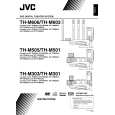
3.4.4 Removing the heat sink bracket (See Fig.5) � Prior to performing the following procedure, remove the amplifier assembly. (1) From the top side of the amplifier assembly, remove the three screws G and three screws H attaching the heat sink bracket. (2) Take out the heat sink bracket. Reference: When attaching the heat sink bracket, attach the screw H with barrier.
E
C
Fig.4
Amplifier assembly
H
Barrier
Heat sink bracket
Fig.5 3.4.5 Removing the amplifier board (See Fig.6) � Prior to performing the following procedures, remove the amplifier assembly and heat sink bracket. (1) From the top side of the amplifier assembly, disconnect the amplifier board from the connectors CN201 and CN203 on the main board. (2) Take out the amplifier board and disconnect the wire from the connector CN202 on the amplifier board.
G
CN202 Main board
CN203
Fig.6
CN201 Amplifier board
(No.MB198)1-27
 $4.99 TH-M603 JVC
Owner's Manual Complete owner's manual in digital format. The manual will be available for download as PDF file aft… 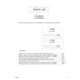 $4.99 TH-M603 JVC
Parts Catalog Parts Catalog only. It's available in PDF format. Useful, if Your equipment is broken and You need t…
|
|
|
> |
|