|
|
|
Categories
|
|
Information
|
|
Featured Product
|
|
|
 |
|
|
There are currently no product reviews.
 ;
Excellent manual, detailed, very useful! Exactly what I needed, I'd recommend it to all who need it. Although images are scanned easily readable and explicit. A valuable tool product at a price more than modest, take it with confidence and you will not regret it!
;
Clear and complete service manual. Easy now to restore my old Kenwood KD-1500.
Thanks a lot.
;
Thanks for this "hard to find" service manual. This Sony PS212A is a very good turntable that needed to be restored !
 ;
Excellent quality on these manuals. Same as having the original printed manual and incredibly useful when doing a custom install like me. Keep it up on the good work.
;
This is an excellent information source. Great quality and tons of info regarding technical service for the Technics SH8065.
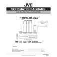
3.4.2 Removing the rear panel (See Figs.3 and 4) � Prior to performing the following procedure, remove the amplifier assembly. (1) From the back side of the amplifier assembly, remove the five screws C, screw D and screw E attaching the rear panel. (See Fig.4) (2) From the top side of the amplifier assembly, take out the rear panel with fan motor, and disconnect the wire from the connector CN202 on the amplifier board. (See Fig.3) 3.4.3 Removing the fan motor (See Fig.4) � Prior to performing the following procedures, remove the amplifier assembly and rear panel. (1) From the front side of the rear panel, remove the four screws F attaching the fan motor. (2) Take out the fan motor.
F
F
C
D
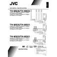
3.4.4 Removing the heat sink bracket (See Fig.5) � Prior to performing the following procedure, remove the amplifier assembly. (1) From the top side of the amplifier assembly, remove the three screws G and three screws H attaching the heat sink bracket. (2) Take out the heat sink bracket. Reference: When attaching the heat sink bracket, attach the screw H with barrier.
E
C
Fig.4
Amplifier assembly
H
Barrier
Heat sink bracket
Fig.5 3.4.5 Removing the amplifier board (See Fig.6) � Prior to performing the following procedures, remove the amplifier assembly and heat sink bracket. (1) From the top side of the amplifier assembly, disconnect the amplifier board from the connectors CN201 and CN203 on the main board. (2) Take out the amplifier board and disconnect the wire from the connector CN202 on the amplifier board.
G
CN202 Main board
CN203
Fig.6
CN201 Amplifier board
(No.MB198)1-27
 $4.99 TH-M606 JVC
Owner's Manual Complete owner's manual in digital format. The manual will be available for download as PDF file aft… 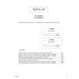 $4.99 TH-M606 JVC
Parts Catalog Parts Catalog only. It's available in PDF format. Useful, if Your equipment is broken and You need t…
|
|
|
> |
|