|
There are currently no product reviews.
 ;
I found this manual to be complete in every detail. Besides the schematic it has a complete set of alignment instructions which are easy to understand. It also includes a complete parts list as well as an explanation of how the power supply and safety shutdown circuits operate. Even a schematic of the tuner is included.
 ;
The product was good and just what I needed, however I had moderate difficulty with the down load because the sight would not recognize my pass word. I was finally given a direct link to the manual and that worked.
;
Very quick and easy website to use and fast download of manual, quality of manual is excellent and will be pleased to use this service again in the future, thanks so much!
;
It is an very good and clear scanned service manual.
very recommended.
;
Easy to order the manual. Good quality and fast delivery.
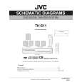
3.1.9 Removing the main board (See Figs.14 and 15) � Remove the metal cover, video board and heat sink with power amp. boards. (1) From the top side of the main body, disconnect the card wires from the connectors CN400, CN401 and CN403 to CN405, on the main board. (See Fig.14.) (2) Disconnect the wires from the connectors CN102, CN101 on the main board. (See Fig.14.) Reference: After connecting the wires, fix the wires with the wire clamp. (3) Remove the two screws P attaching the main board to the chassis base. (See Fig.14.) (4) From the back side of the main body, remove the three screws Q attaching the main board to the rear panel. (See Fig.15.) (5) Take out the main board from the main body.
Wire clamp
CN405 CN403 CN404
P
CN102 CN400
P
CN110
CN401
Fig.14
Rear panel
Q
Fig.15
(No.MB413)1-13
 $4.99 TH-S11 JVC
Circuit Diagrams Set of circuit diagrams. The diagrams will be provided as PDF file. The file will be delivered after…  $4.99 TH-S11 JVC
Parts Catalog Parts Catalog only. It's available in PDF format. Useful, if Your equipment is broken and You need t…
|