|
|
|
Categories
|
|
Information
|
|
Featured Product
|
|
|
 |
|
|
There are currently no product reviews.
 ;
I am very pleased with the service manual for my RT-909. This was an easy purchase and great procuct, and much cheaper than other venues i had looked at. This web site is now listed in my favorites list. KEEP UP THE GOOD WORK. THANKS. J. BROWN
;
A very well written and easy to understand manual.
;
There was no problem at all.After paying i had to wait only a few hours,than i could
download the manual in best pdf-quality.
Thank You !
 ;
I found this service manual to be complete in every detail except for troubleshooting charts. It would be helpful if it had a set of troubleshooting charts; however it is a very good manual otherwise and for the price it is very well worth it.
;
Complete manual included schematics layouts and alignment procedure, clear to read and magnify, extremely pleased with manual and owner manual . com's service
3.3
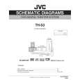
Subwoofer section
3.3.1 Removing the cloth frame assembly (See Fig.1) (1) From the right side of the subwoofer main body, release the joints a to remove the cloth frame assembly. (2) Remove the cloth frame assembly from the subwoofer main body. Reference: When attaching the cloth frame assembly, apply the bonds to the claws a of the cloth frame assembly.
Cloth frame assembly a
a
Fig.1 3.3.2 Removing the woofer unit (See Figs.2 and 3) � Remove the cloth frame assembly. (1) Remove the four screws A attaching the woofer unit. (See Fig.2.) (2) Take out the woofer unit from the subwoofer main body. (3) From the back side of the woofer unit, disconnect the wire from the terminal. (See Fig.3.)
Woofer unit
A
A
Fig.2
Woofer unit
Terminal
Fig.3 1-20 (No.MB193)
Wire
 $4.99 TH-S3 JVC
Circuit Diagrams Set of circuit diagrams. The diagrams will be provided as PDF file. The file will be delivered after…  $4.99 TH-S3 JVC
Owner's Manual Complete owner's manual in digital format. The manual will be available for download as PDF file aft…  $4.99 TH-S3 JVC
Parts Catalog Parts Catalog only. It's available in PDF format. Useful, if Your equipment is broken and You need t…
|
|
|
> |
|