|
|
|
Categories
|
|
Information
|
|
Featured Product
|
|
|
 |
|
|
There are currently no product reviews.
 ;
It´s very very nice manual with all, what i need. Original in good quality. Very fast business. Very much thanks...
;
Purchased the manual that I was looking for at a great price and could download it easily.. Great service experience and for future purchases I plan to use the site.
Thank you very much
;
Exactly what was needed to assess the product - excellent value and great service
;
A site where discontinualed schematic diagrams and back dated information can be found on discontinued radios tv's and any electronic equipment can be found. Newer manuals either Service and operating manuals. Radio amateurs should find this site a great source for ham radio equipment manuals. I will return to this site should I need information on any electrical equipment. priced easy to download in a PDF format and print pages need to undertake the repair.
;
Quality scan of the original. All the detail necessary to troubleshoot, repair and adjust the unit. I'm sure I will be downloading more manuals in the future as the need arises.
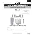
TH-V70 Removing the main board (See Figs. 11 and 12.)
Remove the top plate. Remove the bottom panel. Remove the top panel. Remove the DVD mechanism assembly. Remove the front panel assembly. Remove the DSP/Audio board.
Main board
M
Insert this wire into the notch. Compulink board Tuner Card wire
CN592 CN805 CN972
M
Fan motor wire Wire clamp
M
1. Disconnect the card wire from connector CN805 on the main board. 2. Remove the wire clamp bundling the fan motor wire and then disconnect the wire from connector CN972 on the main board. 3. Disconnect the card wire from connector CN592 on the compulink board. 4. Remove the five screws M and screw M' attaching the main board. 5. From the rear side of the main body, remove the three screws N attaching the main board. 6. Remove the rear panel with the tuner and compulink board. 7. Take out the main board from the bottom chassis. [Reference] Attaching the main board When attaching the screw M', attach the wire holder together with it. After connecting the wires to the connectors, bundle them using the wire clamp. Insert the DVD mechanism assembly wire into the notch on the bottom chassis. (See Fig. 11.) Fig.12
Wire holder
M'
Fig.11
Rear panel
M
N
Fan motor wire
Wire clamp Tie band
CN972
Removing the fan motor (See Figs. 13 and 14.)
Remove the top plate. Remove the bottom panel. Remove the top panel. Remove the DVD mechanism assembly. 1. Remove the wire clamp and tie band bundling the fan motor wire. 2. Disconnect the wire from connector CN972 on the main board. 3. From the left side of the main body, remove the two screws P attaching the fan motor. [Reference] After mounting the fan motor, bundle the fan motor wire using the wire clamp. Fig.13
Bottom chassis
Fan motor
Front panel assembly
P
Fig.14 1-9
 $4.99 TH-V70 JVC
Circuit Diagrams Set of circuit diagrams. The diagrams will be provided as PDF file. The file will be delivered after… 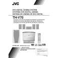 $4.99 TH-V70 JVC
Owner's Manual Complete owner's manual in digital format. The manual will be available for download as PDF file aft…  $4.99 TH-V70 JVC
Parts Catalog Parts Catalog only. It's available in PDF format. Useful, if Your equipment is broken and You need t…
|
|
|
> |
|