|
|
|
Categories
|
|
Information
|
|
Featured Product
|
|
|
 |
|
|
There are currently no product reviews.
 ;
Excellent printing quality.
A complete and very usefull service manual with all details.
GREAT SERVICE AT VERY LOW PRICE!
A+++++++++++++++++++++++++
;
Very fast and perfect delivery. Clear and well scanned. A lot of work professionally realized.
Again thak you a lot
 ;
This manual is accurate and of high quality. It is only volume 2 of the service manual. This is schematic, parts lists, and exploded mechanical drawings. The theory of operation and the diss-assembly instructions are in volume 1. The unit can be tricky to dis-assemble portions of so the volume 1 manual can be important. The product description of the manual is accurate but it does not say anything about volume 1 and the image of the front page does clearly say Volume 2.
;
Wellll again thank you very much fast and effective. Clear and well done for such an old TV!!!!
;
It has all the information you will need to fix it. The main circuit diagram is only A4 but being a PDF, you can print it to any size - I did it on two sheets of A3 and it didnt lose any detail - just made it readable when pinned up above the bench. I've found the fault, just need to buy some obscure bits to get it going again!
I cant fault the process, I paid for the manual in the morning and it was ready to download by lunch time.
TK-2202/2206
CIRCUIT DESCRIPTION
6) Squelch
Part of the AF signal from the IC enters the FM IC (IC201) again, and the noise component is amplified and rectified by a filter and an amplifier to produce a DC voltage corresponding to the noise level. The DC signal from the FM IC goes to the analog port of the microprocessor (IC405). IC405 determines whether to output sounds from the speaker by checking whether the input voltage is higher or lower than the preset value. To output sounds from the speaker, IC405 sends a high signal to the SP MUTE line and turns IC302 on through Q303,Q304,Q305,Q306 and Q316. (See Fig. 4)
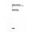
2) VCO
The operating frequency is generated by Q4 in transmit mode and Q3 in receive mode. The oscillator frequency is controlled by applying the VCO control voltage, obtained from the phase comparator, to the varactor diodes (D4 and D7 in transmit mode and D5 and D9 in receive mode). The RX pin is set high in receive mode causing Q5 turn on. The TX pin is set high in transmit mode. The outputs from Q3 and Q4 are amplified by Q6 and sent to the RF amplifiers.
D4, 7 LPF
Q4 TX VCO
Q2 BUFFER
7) Receive Signalling
(1) QT/DQT The output signal from FM IC(IC201) enters the microprocessor(IC405) through IC301. IC405 determines whether the QT or DQT matches the preset value, and controls the SP MUTE and the speaker output sounds according to the squelch results. (2) MSK (Fleet Sync) The MSK input signal from the FM IC goes to pin 31 of IC 301. The signal is demodulated by MSK demodulator in IC 301. The demodulated data goes to the CPU for processing.
RECEIVE SIGNALLING IC301 FM IF IC201 IF Amp SIGNAL DTMF QT/DQT AQUA
LPF
Q6 BUFF AMP
IC2 1/ 2
D5, 9
Q3 RX VCO
Q5, 7 T/R SW RX TX
PLL IC IC1
1N
5kHz/6.25kHz
PLL DATA PHASE COMPARATOR REF OSC 1M 5kHz/6.25kHz CHARGE PUMP
X1 12.8MHz
IC405 BUSY QT/DQT IN CLK,DATA, STD,LOADN CPU Q303,304,305 SW AF CONT IC302 AF PA Q306,316 SW SP
Fig. 5 PLL circuit
3) Unlock Detector
If a pulse signal appears at the LD pin of IC1, an unlock condition occurs, and the DC voltage obtained from C4,R5 and D1 causes the voltage applied to the microprocessor to go low. When the microprocessor detects this condition, the transmitter is disabled, ignoring the push-to-talk switch input signal.
Fig. 4 AF amplifier and squelch
(3) DTMF The DTMF input signal from the FM IC (IC201) goes to IC301. The decoded information is then processed by the CPU.
4. Transmitter System 3. PLL Frequency Synthesizer
The PLL circuit generates the first local oscillator signal for reception and the RF signal for transmission.
1) Microphone Amplifier
The signal from the microphone passes through the IC301. When encoding DTMF, it is turned OFF for muting the microphone input signal by IC301. The signal passes through the Audio processor (IC301) for the maximum deviation adjustment, and goes to the VCO modulation input.
1) PLL
The frequency step of the PLL circuit is 2.5, 5, 6.25 or 7.5kHz. A 12.8MHz reference oscillator signal is divided at IC1 by a fixed counter to produce an oscillator (VCO) output signal which is buffer amplified by Q2 then divided in IC1 by a programmable counter. The divided signal is compared in phase with the 5 or 6.25kHz reference signal from the phase comparator in IC1. The output signal from the phase comparator is filtered through a low-pass filter and passed to the VCO to control the oscillator frequency. (See Fig. 5)
9
|
|
|
> |
|