|
|
|
Categories
|
|
Information
|
|
Featured Product
|
|
|
 |
|
|
There are currently no product reviews.
 ;
Excellent had everything I wanted, very happy with purchase
 ;
This service is relatively cheap, document is fast available, schematic is readable.
Thanks.
;
So far I´m a satisfied customer. I have only downloaded "TECHNICS SX-KN470 Service Manual" maybe I will use it later.
Best regards
Peter
;
Good manual. It is complete and of high quality, both text and graphics. The schematics are with the original big size, so it can be viewed or printed without any loss of resulution and sharpness.
;
We needed a manual quickly...online it was available immediately, at a very low price. We loved the convenience!
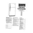
TK-790/(B)/H(B)
DISASSEMBLY FOR REPAIR (TK-790H(B))
1. Removing the Case and Shield Cover
1. Remove the 12 screws ( 1 ), and remove the upper and lower halves of the case. (Remove the 6 screws holding the upper half and the 6 screws holding the lower half.) 2. Remove the 2 screws ( 2 ), and remove the shield cover.
3. Removing the Final Unit (X45-356)
1. Remove the 2 hexagonal bosses ( 5 ). 2. Remove the 3 screws ( 6 ) holding the power module and transistor to the frame. 3. Desolder the power module. 4. Remove the 1 screw ( 7 ) holding TH1. 5. Remove the 4 screws ( 7 ) holding the final transistor. 6. Remove the 2 screws ( 8 ) holding the lead terminal from DC connector (4P) on the rear. 7. Remove the 13 screws ( 9 ) holding the PC board. 8. Desolder W3 on the antenna connector.
2. Removing the TX-RX Unit (X57-561 A/3)
1. Remove the 7 screws ( 3 ), and remove the PLL shield case. 2. Remove the connector (CN201) and coaxial plugs (CN104, CN203) from the final unit, and remove the flat cable (CN202) upwards from the control unit (CN502). 3. Remove the 5 screws ( 4 ).
1 1 1 1
1
2
8 9 9 6 9 7 9 6 6 CN203 3 3 3 3 4 4 3 CN104 CN201 9 Final unit 9 5 9 9 9
8
3 3 4
44 TX-RX unit
Control unit
1 1 1 1
23
|
|
|
> |
|