|
|
|
Categories
|
|
Information
|
|
Featured Product
|
|
|
 |
|
|
There are currently no product reviews.
 ;
This is a great site. I placed my order and by the next am it was available for download. Had some problems with some missing copy on some pages. Once I brought the error to the OMC's attention, the issue was resolved. I'll come back again.
 ;
Mi spiace per non poter scrivere in inglese... ma sono veramente soddisfatto del servizio offerto. Grazie..!!
;
The quality of this manual is good. It has all schematics and setup information for both the MDS-B3 and the MDS-B4. The scan quality is quite good, all pages are readable, This service manual also contains scans of the operating instructions from the User manual.
;
Quick site processing. A complete and very useful manual with all details. Thank you!
;
Das Service Manual war von der ersten bis zur letzten Seite sehr informativ und hilfreich. Die Darstellung aller Teile war klar und der Text gut lesbar.
Vielen Dank, das war nicht der letzte Download bei ownner-manuals.com.
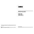
TK-890/(B)/H(B)
DISASSEMBLY FOR REPAIR
6. Disassembly of the Display Unit (X54-3190) : KCH-10
1. Pull out the VOL and UP/DOWN knobs ( 1 ). 2. Remove the 2 hexagnal nuts ( 2 ). 3. Disconnect the 2 connectors (CN2 and CN4) of the display unit (X54-3190 A/3). You can remove the UP/ DOWN encoder ( 3 ). 4. Remove the waterproof seal ( 4 ). 5. Remove the 4 screws ( 5 ) holding the speaker and PC board fitting. 6. Remove the 3 screws ( 6 ). You can remove the display units (X54-3190 A/3 and C/3) ( 7 and 8 ). 7. Remove the 3 screws ( 9 ), and remove the sub-panel ( 10 ) and keytop ( 11 ).
7. Disassembly of the Display Unit (X54-3200) : KCH-11
1. 2. 3. 4. Pull out the VOL and UP/DOWN knobs ( 1 ). Remove the 2 hexagnal nuts ( 2 ). Remove the waterproof seal ( 3 ). Disconnect the connector (CN4) of the display unit (X543200 A/2), and remove the 5 screws ( 4 ). you can remove the up/down encoder ( 5 ) and display unit. 5. Remove the 4 screws ( 6 ), and remove the sub-panel ( 7 ) and keytop ( 8 ).
B/2
4 5 CN4
B/3 A/2
6 7 CN2
A/3
3 6 CN4 5 6 6 9 9
C/3
4
8 7 9 8 10 3 11 2 4 1 2 2 1 2
25
|
|
|
> |
|