|
There are currently no product reviews.
 ;
Fast Download,all pages present,an excellent copy.THis enabled to find the origional part numbers and chase them up. The cartridge is proving difficult to find but at least I know the origional part number.Thanks to all.
;
The manual was as described. Complete with parts list and technical information. Fast delivery.
 ;
Simple and fast...
The diagrams are clear and legible; i have been a great help.
The site is very reliable and precise thanks.
;
Very easy site. Great service and quick release for download. Manuals are of good quality.
Joop - The Netherlands
;
Very good manual, in depth and complete. Only criticism is that some of the circuit diagrams are slightly blurry and hard to follow for long periods of time, but this is to be expected. Perfect for any maintenance required. Also contains the wiring diagrams of the control cable for constructing extensions.
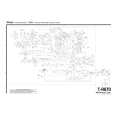
1. AM TRACKING VOLTAGE ADJUSTMENTS
DC VOLTMETER ........................... CONNECT TO TEST POINT P5 and GND
NO. 1 2
P5
Band AM AM
Frequency 530KHz 1720KHz
Adjust for 2.2V 9.5V
Adjustment T1 TVC1
GND
2. AM RF ADJUSTMENT
Signal Generator ........................ Connects to the AM ANT. Coil through the loop antenna. Adjust for the indication of VTVM of the wave form of scope to be maximum. BAND Step 1 AM 2 3 Frequency 630KHz 1420KHz Adjust for Maximum sensitivity Maximum sensitivity Repeat steps 1 and 2 several times. Adjustment L2, T2 TVC2
3. FM 19kHz REJECTION ADJUSTMENT
NO. 1 2 3 Frequency 97.8MHz 97.8MHz 97.8MHz Adjust for L rejection R rejection L, R rejection Adjustment T4 T5 TVR3
�4�
 $4.99 TR670 TEAC
Owner's Manual Complete owner's manual in digital format. The manual will be available for download as PDF file aft…
|