|
|
|
Categories
|
|
Information
|
|
Featured Product
|
|
|
 |
|
|
There are currently no product reviews.
 ;
complete wiring diagram, without the part list. high quality copy. thanks for promptly.
;
Well done scan of a useful manual. It will be useful in my workbench!!
 ;
Excelent scan job. It's a fully detailed service manual of this model.
;
Do a quick order, scan quality is high.
I recommend to all!
;
This manual is perfect! Just what I needed. Thanks!
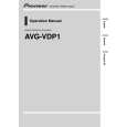
BLOCK DIAGRAM
Antenna
3 1 TU200 Tuner 2 Q200 IF Amp.
IC200 4 Video Sound Det. FM AFT Circuit AGC Circuit VR600 Audio Amp. Volume Control IC600 Speaker
7
IC500
5
IC300 Chroma Circuit Common Driver LCD
Tuning Voltage Generator
6
IC700 Osc. Display Control A-D Converter Auto-Tuning Control
Segment Driver
VR800
8
Q800 ~ Q806, Q810, Q811 Display Voltage Generator
Power Supply
VCC2 (4.3 ± 0.02 V) VCC7 (41.6 ~ 51.6 V) VEE1 (-6.5 ~ -8.0 V)
Brightness Control
1 � Color Tuner: TU200 TEPE5-02 Selects a desired radio wave and changes it to the video IF signal. 2 � Video IF Amp.: Q200 2SC4238 Amplifies the video IF signal output from the tuner TU by 10 times (20 dB). 3 � Video Det./Sound Det./FM Det./AFT/AGC: IC200 M51348FP Eliminates the carrier wave in the video IF signal, and picks up the video signal and the sound IF signal. Also, the sound signal is picked up from the sound IF signal by FM detection. 4 � Audio Amp.: IC600 NJM2070M Sound amplification. 5 � Chroma Circuit: IC300 M52045FP Generates the tricolor (red, green, and blue) from the video signal. 6 � Osc./A-D Converter/Display Control/ Auto-Tuning Control : IC700 MSM6625-01 GSK-640E Converts the color signal into a digital signal. Also, generates the clock pulse for the display and controls the display. 7 � Tuning Voltage Generator: IC500 MSC1169MS-K Generates the tuning voltage with the tuning pulse (TU) output from 6. 8 � Display Voltage Generator: IC800 BA10358F, Q800 ~ Q806 Q810 Q811 2SD1149-S, 2SD601A-R�3, 2SB709A-R Generates the display voltages V0 ~ V4 with VEE1 and VCC7 outputs from the power supply.
�2�
|
|
|
> |
|