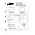
|
There are currently no product reviews.
 ;
Information was accurate and very helpful.
However the continuity made it a little difficult to follow from one page to the next.
 ;
Very very good as usual very trustable site. Perfect!!!!!!
;
The Service Manual received was helpful. Good copy of original document.. I recomend all of my friends about this technical page.
;
Perfect, complete manual, exactly what I needed. Recommended to everyone.
;
Very usefull manual. From my point of view there are needs more clearables images.
HOW TO MOVE THE CHASSIS INTO SERVICE POSITION
1. 2. 3. 4. 5. 6. 7. 8. Remove the bead clamper from the mains lead and attach to the degauss coil, shown in Fig.5. Hold and lift the rear of the E-PCB chassis and gently pull the chassis toward you, as shown in Fig.4. Release the respective wiring clips and rotate the chassis horizontally through 90°, anti-clockwise. Move the EHT lead around to the left side of the CRT neck. Elevate the front of the chassis. Clip the chassis frame onto the bead clamper, on the degauss coil, as shown in Fig.5. Locate the base of the chassis frame into the hole (marked A), shown in Fig.6. After servicing replace the bead clamper and ensure all wiring is returned to its original position before returning the receiver to the customer.
Fig.4.
Fig.5.
Fig.6. (A)
4
|