|
There are currently no product reviews.
 ;
Paid for service manual & got the download fast - worth a visit if you need a service manual
;
It's the manual, I am searching for. Now I am able to repair my Braun A501.
 ;
Great service manual. Unfortunately on page no. 41 there are some details which i can't read.
;
Wonderful service... doubt that I could have made the repairs to my turntable without this service manual. Great help!
Well worth the price paid!
;
nice completed SERVICE MANUAL as the description THANK YOU !!!-
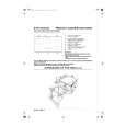
HOW TO MOVE THE CHASSIS INTO SERVICE POSITION
1. Remove the bead clamper from the mains lead and affix, using back cover screw, into top right-hand cabinet rib (A), shown in Fig.4. 2. Remove 2 screws (B), as shown in Fig.5, and remove speaker assembly. 3. Hold and lift the rear of the chassis and gently pull the chassis toward you, as shown in Fig.4. 4. Release the respective wiring clips and rotate the chassis vertically through 90°, anti-clockwise. 5. Locate the base of the chassis frame into location (C), shown in Fig.6 / Fig.8. 6. Clip the chassis frame onto the bead clamper, shown in Fig.6 / Fig.7. 7. After servicing replace the bead clamper and speaker, and ensure all wiring is returned to its original position before returning the receiver to the customer. (A)
Fig.4.
Fig.5.
Screws (B)
Fig.5. Fig.7.
a
Fig.6.
(C) Fig.8.
4
|