|
|
|
Categories
|
|
Information
|
|
Featured Product
|
|
|
 |
|
|
There are currently no product reviews.
 ;
I'm very satisfied with your manual service. Your website made it easy to locate the correct manual. Also the quality is great and I never had a problem reading the fine details.
Thanks again.
Jeff Miller
JM Electronics
 ;
Good quality service manual German user manual. German user manual This is a quality scan of a manual in excellent condition and is just as good as having the original manual in hand
;
The manual for Sony LBT-D505 component stereo system is was excellent , with schematics, parts layout and parts list as well as instructions for adjustments for each component. Print was clear even when enlarged.
;
It's exactly a complete and very useful manual with all details what I needed. Thank you!I will come back whenever I need your manuals or schematics.
;
I searched EVERYWHERE looking for the manual/s on this "extinct" amp. Owner-Manuals.com made it available and for nearly nothing. Thanx to them, I can decipher the unknown cables and sort them out. Thanx, Owner-Manuals.com!!
TX-SR700/E ADJUSTMENT AND CONFIRMATION PROCEDURES 2
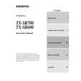
3. Confirmation of Current detection circuit Set the unit to "Test-1-00". Connect the differentiating circuit and apply the 200Hz square signal to MULTI CHANNEL INPUT terminal of each channel. Adjust the attenuator or Volume so that the output level becomes 35V p-p. Confirm that the speaker relay does not turn OFF when a 3.0 ohm load is connected. Confirm that the speaker relay turns off when a 1.5 ohm load is connected. Caution:Don't continue more than 3 seconds.
CR OSCILLATOR DIFFERENTIATING CIRCUIT 200Hz SQUARE OSCILLOSCOPE ATTENUATOR MULTI CHANNEL INPUT SPEAKER TERMINAL UNIT
INPUT
3.3k
0.1 F
1SS133x6
3.3k
OUTPUT 10k GND 0.01 F
35Vp-p
Test Mode
Differentiating Circuit
1. Turn POWER button on. 2. Press and hold down CD button, then press STANDBY/ON button. 3. After "Test-1" on the FL tube is displayed, press CD button to set the unit to the Test mode of FL tube.
Note: DVD:Test-1 VIDEO 1 :Test-2 ZONE 2: UP VIDEO 2 :Test-3 VIDEO 3:Test-4 REC OUT: DOWN
Test mode of FL tube
All segments light on.
ZONE 2
REC OUT
Test-X YZ
FL TUBE Item
"FEDCBA987654321" light on.
The segments of odd number light on .
The segments of even number light on .
"Good-bye **" light on.
**: Region US:U.S.A. EU:Europe WR:Other models Press POWER button to finish the Test mode of FL tube.
Confirmation of voltage sensor 1. Set the unit to Test-3-4. 2. Apply the signal 1kHz, -15dBV to the MULTI-CH input. Confirm that the FM STEREO is displayed. Confirm the all channels except SUBWOFFER. 3. When connect the resistor 2.7 kohm/1 W between the terminals COM and TH1 of P6301, confirm that "FM STEREO" light on. Note: No input signal. 4.When set the unit to "Test-4-30,confirm that the speaker relays of RL6901 and RL6902 turn off. Note: No input signal.
Page 54
|
|
|
> |
|