|
|
|
Categories
|
|
Information
|
|
Featured Product
|
|
|
 |
|
|
There are currently no product reviews.
 ;
It's a full manual. All the parts are in there. I haven't found the problem yett, but I am working on it; hope I can rebuild the part myself. To make it more secure and unbreakable this time. Because the part has failed several times before and costs a lot to let it be repaired.
Thanks so much for this rich illustrated and parted manual.
;
I downloaded the document. The manual was complete, well scanned and everything was legible. I could zoom in see what I needed to know. There's not much more that you can ask.
;
It was complete service manual with all needed service informations. Thanks.
 ;
El manual esta muy detallado, los numeros de partes y los esquemas de despiece son correctísimos y muy claros, tanto para los técnicos experimentados como para los novatos.
;
Ottima qualità grafica e completo nelle notizie. Costo abbastanza contenuto.
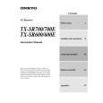
TX-SR700/E ADJUSTMENT AND CONFIRMATION PROCEDURES 2
3. Confirmation of Current detection circuit Set the unit to "Test-1-00". Connect the differentiating circuit and apply the 200Hz square signal to MULTI CHANNEL INPUT terminal of each channel. Adjust the attenuator or Volume so that the output level becomes 35V p-p. Confirm that the speaker relay does not turn OFF when a 3.0 ohm load is connected. Confirm that the speaker relay turns off when a 1.5 ohm load is connected. Caution:Don't continue more than 3 seconds.
CR OSCILLATOR DIFFERENTIATING CIRCUIT 200Hz SQUARE OSCILLOSCOPE ATTENUATOR MULTI CHANNEL INPUT SPEAKER TERMINAL UNIT
INPUT
3.3k
0.1 F
1SS133x6
3.3k
OUTPUT 10k GND 0.01 F
35Vp-p
Test Mode
Differentiating Circuit
1. Turn POWER button on. 2. Press and hold down CD button, then press STANDBY/ON button. 3. After "Test-1" on the FL tube is displayed, press CD button to set the unit to the Test mode of FL tube.
Note: DVD:Test-1 VIDEO 1 :Test-2 ZONE 2: UP VIDEO 2 :Test-3 VIDEO 3:Test-4 REC OUT: DOWN
Test mode of FL tube
All segments light on.
ZONE 2
REC OUT
Test-X YZ
FL TUBE Item
"FEDCBA987654321" light on.
The segments of odd number light on .
The segments of even number light on .
"Good-bye **" light on.
**: Region US:U.S.A. EU:Europe WR:Other models Press POWER button to finish the Test mode of FL tube.
Confirmation of voltage sensor 1. Set the unit to Test-3-4. 2. Apply the signal 1kHz, -15dBV to the MULTI-CH input. Confirm that the FM STEREO is displayed. Confirm the all channels except SUBWOFFER. 3. When connect the resistor 2.7 kohm/1 W between the terminals COM and TH1 of P6301, confirm that "FM STEREO" light on. Note: No input signal. 4.When set the unit to "Test-4-30,confirm that the speaker relays of RL6901 and RL6902 turn off. Note: No input signal.
Page 54
|
|
|
> |
|