|
|
|
Categories
|
|
Information
|
|
Featured Product
|
|
|
 |
|
|
There are currently no product reviews.
 ;
The AKAI 1720 model reel to reel tape recorder described in this Manual is quite an old unit - circa late 1960's. As a consequence, the description of the mechanical details - and adjustments thereof - is quite critical. The manual does this quite well. The schematics are also well presented and have detailed PCB overlays. Probably the only negative is that some half-tone detail has been lost from the original manual as it has been scanned in simple B&W.
 ;
Perfect source for service manuals: fast and professional transaction; high quality, perfect readable and largely scaleable PDF; complete schemes, diagrams and spare part list. Tnx a lot, cu again!!!!
;
I got your link from a friend and I must say that I am really satisfied with your service. Specially this B&O manual I didn't find anywhere on the web... but you could deliver it :-) . You deliver very fast and the copy is of good quality. So your webpage is bookmarked. Thanks
;
This was the Sony CCU-500A Service manual I was looking for.
The price was reasonable.
The permission to download was quck.
I will use Owner-Manual.com for all my manual needs.
;
Excellent printing quality.
A complete and very usefull service manual with all details.
GREAT SERVICE AT VERY LOW PRICE!
A+++++++++++++++++++++++++
(2) Target Sector Read Test [Test condition setting] � Test area setting
4-2-5. Test Display
(1) Floppy Disk Test menu display
Floppy Disk Drive Diagnostics
Cylinder Head Sector
: The cylinder number to be checked is set in the range of 000 79. : The head number to be checked is set in the range of 00 1. : The sector number to be checked is set in the range of 000 18 (9).
Sequential read only test Target Sector read test Sequential write/read & Compare test Target sector write/read & Compare test Error table display
� Retry number setting (0 ~ 4) The retry number in case of an error is set. � Error Stop/Continue/1 pass In case of an error, selection is made whether interrupt is made or not. Also used to select whether the test is executed or not by 1 pass. [Test contents] The sequential read test for every one track is executed in the range set as above. Completion of the read test in the set range is counted as 1 pass. The operation of this test is as shown below:
Sequential read only test
:FMove
ENTER:Select
ESC:Exit
On the above menu, use [ 2 ] and [ 4 ] keys to select a test item. Press [ENTER] key to execute the test. When [ESC] key is pressed, the display returns to the initial menu. (2) Sequential read only test execution display
Re-calibration
Seek to the track to be tested
Lead test
becoming
Drive_A(1.44MB)test ? [ Yes No] Cylinder scope ?
Error Kinds Bad command
Drive_A xxxxx xxxxx
These procedures are repeated.
(3) Sequential Write/Read & Compare Test [Test condition setting] Similar to the above (2). However, the cylinder set range is 01 0 79. [Test contents] The worst pattern data are written into each track in all the set range. Then perform the read/verify check. When the write/read test in the set range in the direction of 0 0 79 cylinder is completed, it is considered as 1 pass. The operation of this test is as shown below:
Drive_A [00 Sector count ?
79] 00 - 79 Bad Address Mark
Drive_A [1,3,9] = 9 Retry Count ? [0 Error stop ? 4] = 0 Recalibrate error Test mode : Read xxxxx Test drive : Drive_A
[error stop continue 1 pass] Test Start [ Yes No] Pass count = xxxxx Test Point=CC,H,SS (Cylinder, head, celector) TIME HH:MM:SS (hour : minute : sound) ESC:Exit
Error details content
SPACE:Stop or Start
Write to all the Re-calibration set range.
Read/verify test in all the set rage
becoming
Select an item in each position indicated with " " (In the above display, the item surrounded by a is selected and the value surrounded by a is selected.) When, in the above display, "Pass count" is counted up (when the test point is counted from 00.0.01 to 79.1.10, Pass count is counted up by 1) and all the error counters of all the error kinds are not counted up (remaining at 00000), the test is OK. During execution of the test, when [SPACE] key is pressed, the test is interrupted. During interruption of the test, when [SPACE] key is pressed, the test is resumed. During execution or interruption of the test, when [ESC] key is pressed, the display returns to the menu of (1).
These procedures are repeated.
When writing data, write different data from those originally stored. (Worst pattern data) Word data: There are two kinds of data: B6DBh, 6DB6h. (4) Target Sector Write/Read-Compare Test [Test condition setting] Similar to the above (2). However, setting of the retry number is omitted. [Test contents] The write/read test in the set range is executed. When the write/read test in the set range is completed, it is considered as 1 pass. The operation of this test is as shown below:
Re-calibration
Seek to the track to be tested
Date write
Read/ becoming verify
These procedures are repeated.
(5) Error table display The error contents generated in procedures (1) ~ (4) are displayed for each test item. The display items are test item, test condition, drive, cylinder, head, sector, error contents, and hour/minute/second. The maximum number of display items is 50 for each test.
UP-X500U DIagnostics Specifications
4�3
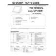 $4.99 UP-X500 SHARP
Parts Catalog Parts Catalog only. It's available in PDF format. Useful, if Your equipment is broken and You need t…
|
|
|
> |
|