|
|
|
Categories
|
|
Information
|
|
Featured Product
|
|
|
 |
|
|
There are currently no product reviews.
 ;
It is wonderful done!!! a great job in scanning the manual. Superior quality in all the electric scheme. Very understandable and net!!! Thank you!
 ;
muy buen manual por lo completo de este algunos esquemas estan muy divididos lo que hace algo dificil el seguimiento.
;
very good manual, with detail and clarity in esquematic diagrams and waveforms .
;
Very quality copy of original service manual, which contains the circuit diagrams, PCB and lists of components, well as recommendation for calibration procedures of device, also everything else, that need for repair, tuning and use this oscilloscope.
All presented copies have high-resolution, so you can view all in detail.
This manual will very useful for simple owners and for repairers.
I recommend these manual, because myself is owner of Philips PM3216 and I need sometimes servicing these oscilloscope (principally calibrating).
Also, these document is an example of excellent design of technical documentation.
;
Excellent printing quality.
A complete and very usefull service manual with all details.
GREAT SERVICE AT VERY LOW PRICE!
A+++++++++++++++++++++++++
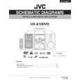
UX-A10DVD
Removing the main board (See Fig.24,25)
Prior to performing the following procedure, remove the metal cover, the DVD mechanism assembly, the front panel assembly and the rear cover/ rear panel. 1. Remove the two screws N and the three screws O. Remove the heat sink. 2. Disconnect the wires from connector CN307 and CN310, the card wire from CN312 on the main board on the left side of the body. 3. Remove the screw board. P and Q attaching the main Fig.24
CN303 CN304 Main board CN305 CN306 Heat sink Heat sink Main board
O N
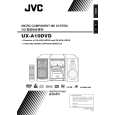
4. Disconnect connector CN303, CN304, CN305 and CN306 on the main board. Release the two joints e at the bottom. 5. Draw out the main board and disconnect the card wire and the wire from connector CN302 and CN311.
CN302 CN312 CN307
P
CN311 e e CN310
Q
Fig.25
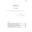
Removing the DVD relay board (See Fig.26)
Prior to performing the following procedure, remove the metal cover, the DVD mechanism assembly and the rear panel/ rear cover. 1. Disconnect the card wire from connector CN515 on the DVD relay board. 2. Remove the screw R attaching the DVD relay board on top of the body. 3. Disconnect connector CN511 and CN512 on the DVD relay board.
CN512 Main board
CN511 DVD connector board
R
CN515
Fig.26
1-10
 $4.99 UX-A10DVD JVC
Parts Catalog Parts Catalog only. It's available in PDF format. Useful, if Your equipment is broken and You need t…
|
|
|
> |
|