|
There are currently no product reviews.
 ;
Quality as promised it arrived fast. No problems what so ever
;
Good scan, very handy and it also includes the user manual. 122 pages in total.
;
This manual was exactly what I needed. Detailed, useful and delivered as promised.
 ;
Great manual good quality really helped in the repair of my Toshiba, thanks
;
Print was clear and easy to read. Thank you Joe joeoldaudio
UX-A52
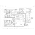
Removing the system control board (See Fig.9)
Prior to performing the following procedure, remove the rear cover, the side panels and the top panel. 1. Disconnect the card wire from connector CN701 and the wire from connector CN706, CN715, CN716 on the system control board. 2. Remove the screw F on the left side of the body. 3. Disconnect connector CN709, CN711 and CN712 on the system control board from the body outward. 4. Disconnect the card wire from connector CN704 on the underside of the system control board.
CN704 CN716 CN715 CN706 CN712 CN711 CN701
CN709
F
System control board
Fig.9
Removing the tuner board (See Fig.10)
Tuner board
Prior to performing the following procedure, remove the rear cover and the right side panel. 1. Disconnect the card wire from connector CN1 on the tuner board on the right side of the body. 2. Remove the screw G and remove the tuner board upward while disengaging the three joints c.
CN1
G
Joints c
Fig.10
1-7
 $4.99 UX-A52 JVC
Circuit Diagrams Set of circuit diagrams. The diagrams will be provided as PDF file. The file will be delivered after… 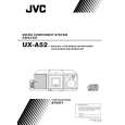 $4.99 UX-A52 JVC
Owner's Manual Complete owner's manual in digital format. The manual will be available for download as PDF file aft…  $4.99 UX-A52 JVC
Parts Catalog Parts Catalog only. It's available in PDF format. Useful, if Your equipment is broken and You need t…
|