|
|
|
Categories
|
|
Information
|
|
Featured Product
|
|
|
 |
|
|
There are currently no product reviews.
 ;
Very good manual. Plenty of service information including alignment instructions. Clear circuit diagram. Excellent, thank you.
 ;
Good morning, the service manual you sent me was perfect.
Your service and answering are excellent.
I recomend this service.
Best regards.
;
I had been looking everywhere for a proper service manual for this VCR. Everywhere else that has this available for download has a very light version. This is the full service manual with all aspects that would interest anyone looking for the service manual for the AIWA HV-MX100 Worldwide VHS VCR. Great quality (as always). A winner hands down. Best Quality.
;
Top quality manual. Covers all aspects you'd expect in a top quality service manual for this Panasonic VHS VCR. The manual resolution is high. Another top quality manual from the only site worth downloading manuals from! If you're looking for a manual for the PV-9662 VHS VCR, this is the one you'll want to get!
;
complete part-lists and pcb layout, schematic diagram is good enlargable,
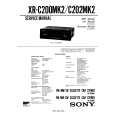
UX-A70MDR Removing the tuner & function board (See Fig.8)
Prior to performing the following procedure, remove the rear cover, the side panels and the top cover. 1. Disconnect the card wire from connector CN701, CN705, CN707, CN708 and CN721 on the tuner & function board on the right side of the body. Similarly, disconnect the harness from CN706. CAUTION: For the card wire connected to CN707, disconnect it after performing the following procedure 2 and 3. 2. Disconnect connector CN711 and CN712 on the tuner & function board from CN801 and CN802 on the main board by pulling them outward. 3. Disconnect connector CN703 and CN704 on the tuner & function board from CN603 and CN604 on the CD servo board by pulling them upward.
CN712 AC jack board CN704 CN701 CN707 CN705 CN721 CN706 CN708
CN703
CN711
Fig.8
Removing the AC jack board (See Fig.9)
Prior to performing the following procedure, remove the rear cover and the right side panel. 1. Remove the screw E on the right side of the body and release the AC jack board from the two joints c. 2. Disconnect the harness from connector CN805 on the AC jack board.
AC jack board Joints c
E
Fig.9
Removing the antenna terminal board (See Fig.10)
Prior to performing the following procedure, remove the rear cover and the left side panel. 1. Disconnect the card wire from connector CN1 on the left side of the body. 2. Remove the screw F and release the antenna terminal board from the joint d upward.
CN1
F
Fig.10
Joint d
Antenna terminal board
1-9
 $4.99 UXA70MDR JVC
Owner's Manual Complete owner's manual in digital format. The manual will be available for download as PDF file aft…
|
|
|
> |
|