|
|
|
Categories
|
|
Information
|
|
Featured Product
|
|
|
 |
|
|
There are currently no product reviews.
 ;
This manual is perfect! Just what I needed. Thanks!
;
This manual was very clear and complete, the prices can't be beat, great to have older manuals available!
 ;
Doubted for buy this manual as it is my first order here and at not have cover image, I assumed would haven't. However, within 24 hs, already possessed the link to download it. The manual are scanned correctly and have all what is needed. Includes adjustments and diagrams of all circuits. Very satisfied.
;
Really good quality, аll readable.! Wonderful work shop. I recommend to all!
;
Good quality service manual.The scheme is on A3 format and very readable.Thank you
3.2.3 Removing the DVD pickup (See Figs.2,4 to 6) � Remove the traverse mechanism assembly. (1) From the side of the traverse mechanism assembly, solder the short land sections a on the DVD pickup. (See Fig.2.) (2) Release the lock of the connector on the DVD pickup in the direction of the arrow and disconnect the card wire. (See Fig.4.) Caution: � Solder the short land sections a on the DVD pickup before disconnecting the card wire from the connector on the DVD pickup. If the card wire is disconnected without attaching solder, the DVD pickup may be destroyed by static electricity. (See Figs.2 and 4.) � When attaching the DVD pickup, be sure to remove solders from the short land sections a after connecting the card wire to the connector on the DVD pickup. (See Figs.2 and 4.) (3) Remove the screw C and remove the feed bracket from the sections d. (See Fig.4.) (4) Release the claw e of the thrust spring in the direction of the arrow and remove the thrust spring. (See Fig.4.) (5) Remove the guide shaft of the DVD pickup from the section f on the traverse mechanism assembly and remove the guide shaft from the section g while moving it in the direction of the arrow. (See Fig.5.) (6) Remove the DVD pickup from the section h of the traverse mechanism assembly and take out the DVD pickup with the guide shaft. (See fig.5.) (7) From the bottom side of the DVD pickup, remove the two screws D attaching the rack arm and rack arm spring. (See Fig.6.) (8) Pull the guide shaft out of the DVD pickup. (See Fig.6.)
Traverse mechanism assembly f Guide shaft Rod spring g
DVD pickup
Fig.5
h
DVD pickup
Rack arm e
Feed bracket d Thrust spring Guide shaft
D
Rack arm spring
C
Fig.6
Card wire Thrust spring
Fig.4
DVD pickup Connector
1-22 (No.MB408)
 $4.99 UX-GD6S JVC
Owner's Manual Complete owner's manual in digital format. The manual will be available for download as PDF file aft… 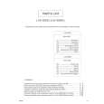 $4.99 UX-GD6S JVC
Parts Catalog Parts Catalog only. It's available in PDF format. Useful, if Your equipment is broken and You need t…
|
|
|
> |
|