|
|
|
Categories
|
|
Information
|
|
Featured Product
|
|
|
 |
|
|
There are currently no product reviews.
 ;
fast and easy and exactly what I was looking for. Not the cheapest but value for money after all.
;
The manual for the Sansui P-L75 was not one of the more informative turntable manuals around but for $5 it was helpful enough.
;
VERY GOOD SERVICE.FAST ANS VERY HONEST PRICE .RHAANK HERNAN
 ;
Thanks to this service manual I repaired my old camcorder! The manual perfectly explains how to disassemble the camcorder step by step.
;
This manual is very useful because it presents the technical specifications of the cd player, including the manufacturer of the reader, this helps if you need to replace it. It also displays the settings and layout of the circuit.
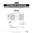
4.1.6 Tuner Section
Item AM IF adjustment Measuring Condition Signal input: Loop ANTENNA Signal output: U201 PIN 16 Signal input: Loop antenna PHONES (with 32 ohm Load) Check and adjustment procedure 1.Set the intermediate frequency sweep generator to AM 450 kHz. 2.Adjust the T201 for maximum and center output. Standard value Adjusting part T201 See Fig 3-3
AM tracking adjustment
1.Set the TUNER at 531 kHz adjust T202 until the test pin of R229 Voltage at 1.5V 0.1V. 2.Set the TUNER at 1710 kHz, Check the pin of R229 Voltage at 8.4V 6V. 3.Set theTUNER and S/G at 603 kHz, adjust T204 for maximum output. 4.Set the TUNER and S/G at 1404 kHz, adjust VC201 for maximum output. 5.Repeat the above steps 3 and 4.
T202 T204 R229
VC201
FM Tracking Adjustment
Signal input point: FM-ANT Phones With 32 ohm load
1.Set the Tuner at 87.5MHz adjust L203 until the test pin of R230 voltage at 2.4V 0.1V 2.Set the Tuner at 108MHz. Check the pin of R230 voltage at 8 0.8V 3.Set the Tuner and S/G at 90.1MHz. Adjust L204 for maximum output. 4.Set the Tuner and S/G at 106.1MHz. Adjust VC 202 for maximum output. 5.Repeat the above step 3 and 4
R230 L204
VC202
1-14 (No.MB066)
 $4.99 UX-H10 JVC
Circuit Diagrams Set of circuit diagrams. The diagrams will be provided as PDF file. The file will be delivered after…  $4.99 UX-H10 JVC
Owner's Manual Complete owner's manual in digital format. The manual will be available for download as PDF file aft…  $4.99 UX-H10 JVC
Parts Catalog Parts Catalog only. It's available in PDF format. Useful, if Your equipment is broken and You need t…
|
|
|
> |
|