|
There are currently no product reviews.
 ;
All ok. I pay 5 $ and now i have 92 pages of good scaned service manual for my oooooold akai. Now i will try to repair it.
;
good and ok, very nice , good and ok, very nice, good and ok, very nice
;
Super manual it contains all the things you need to service your Marantz 2100.
;
A very easy to understand and use manual. Well worth the money.
 ;
Very good information with clear drawings. Thanks!
UX-H33
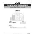
2.2.6 Reattaching the Play/ Record & Clear head (See Fig.11~13) (1) Reattaching the head mount assembly. a) Change front of the direction cover of the head mount assembly to the left (Turn the head forward). b) Fit the bosses O', P', Q', U' and V' on the head mount assembly to the holes P and V, the slots O, U and Q of the mechanism sub assembly (See Fig.11 to 13). CAUTION: To remove the head mount assembly, turn the direction cover to the left to disengage the gear. If the gear can not be disengaged easily, push up the boss Q' slightly and raise the rear side of the head mounts slightly to return the direction lever to the reversing side. (2) Tighten the azimuth screw for reversing. (3) Reattach the spring from the back of the Play / Record & Clear head. (4) Connect the flexible wire to connector CN31 on the head amplifier & mechanism control board.
O' P' V'
U'
Head mount assembly
Fig.11
Q'
Direction cover
Head mount assembly
O PQ V U
Direction cover
Fig.12
Head
Azimuth screw for reversing Head mount
Spring Flexible wire
CN31
Fig.13
Head amplifier & mechanism control board
(No.22044)1-17
 $4.99 UX-H33 JVC
Circuit Diagrams Set of circuit diagrams. The diagrams will be provided as PDF file. The file will be delivered after…  $4.99 UXH33 JVC
Owner's Manual Complete owner's manual in digital format. The manual will be available for download as PDF file aft…  $4.99 UX-H33 JVC
Parts Catalog Parts Catalog only. It's available in PDF format. Useful, if Your equipment is broken and You need t…
|