|
|
|
Categories
|
|
Information
|
|
Featured Product
|
|
|
 |
|
|
There are currently no product reviews.
 ;
I was very pleased with the service provided and was surprised at how good the quality was of the manual. I thought it may be a third generation copy or so, but it is as good as the websites that charge 3 times this much. I repair some electronics for family and friends without charge, so this is perfect for me. Thank you very much.
;
The service was great and the document was also great. Highly recommend!!!!
If anyone has a users manual... Please email me. need one. $ [email protected]
;
I needed a service manual as the display on my oscilloscope was very dim. I thought I'd give owner-manuals.com a try, as they advertised a huge number of manuals. Sure enough they had one listed. I bought it hoping it would be useful... actually, I bought it hoping it would be readable! I've had manuals from online sources in the past, and been very disappointed. Not this time! An excellent manual, complete, and very readable. Using it I fixed my 'scope, and as such the manual was an investment that paid off manyfold. Do I have any complaints? One very minor one - The circuit diagrams could have been scanned at a higher resolution, as some of the details were a little difficult to make out - not impossible, just not as easy as my old eyes would like! Overall, I'm very satisfied with my manual, and I will certainly be using this company again. Well done.
 ;
I Have looked for this manual for quiet a while now, I have finally found it here. I believe this is the only place they have them in a very nice scan, pages are very clear to read, some of the pages are a bit tilted but overall it is great to have this manual available for purchase. Thanks
;
This is quiet a rare manual, I Have looked for this manual for quiet a while now, I have finally found it here. I believe this is the only place they have them in a very nice scan, Excellent guide: very clear, enabling us to print readable diagram overall it is great to have this manual available for purchase. This is a complete service manual no pages are missing. Thanks
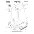
3.1.9 Removing the heat sink/power board (See Fig.20 to 27) � Prior to performing the following procedure, remove the front panel assembly. (1) From the bottom of the rear cover, peel off the tape attaching the wire extending from the power board and remove the earth plate which is attached with the double-sided tape. (2) Remove the four screws T attaching the holder in the power unit section. (3) Move the power unit section with the wire from the rear cover temporarily. If necessary, release the band and unsolder the wire on the power board. (4) Remove the four screws U and the screw Y attaching the holder. (5) Release the wire from the band at �e� and move the holder in the direction of the arrow to release from the joint f. (6) Remove the four screws A� and two screws B� attaching the heat sink. (7) Remove the two screws D� attaching the power board.
Power unit section
T
T
T
T
Power unit section
Rear cover Power trnsfomer assembly
Fig.21
Wire
Rear cover Tape
Fig.20
earth plate
Rear cover Ppwer unit section
Fig.22
(No.MB297)1-15
 $4.99 UX-H350 JVC
Parts Catalog Parts Catalog only. It's available in PDF format. Useful, if Your equipment is broken and You need t…
|
|
|
> |
|