|
|
|
Categories
|
|
Information
|
|
Featured Product
|
|
|
 |
|
|
There are currently no product reviews.
 ;
Very useful service manual, was exactly what i needed.Good quality,reasonable price.Thank you.
;
Acurate informations inside the SM and I could repair my old Sansui SC-3330 without any problems. Thanks.
;
I used it to repair a NAD 7030, but unfortunately, the 7045 is different !
But documentation was useful.
;
Content A4 and A3 format pages. Exactly what I needed to restore my old receiver.
;
Content A4 and A3 format pages. Exactly what I needed to restore my old receiver.
UX-M33
Cassette amplifier section
Item Head azimuth adjustment Measuring condition Test tape: Check and adjustment procedure 1.Play back the test tape VT702 (8kHz). Standard value Output level: Adjusting part Head azimuth VT702 (8kHz) 2.Adjust the head azimuth adjusting screw so that the Signal output terminal: phase difference between the R and L channels is PHONES (with 32 ohm load) minimized at an output level that is within (+2dB-2dB) of the maximum output level. After this adjustment, lock the head azimuth adjusting screw with screw sealant to cover more than a half of the screw head. 3.When the head azimuth is maladjusted, correct it with the head azimuth adjusting screw. Tape speed and wow/flutter check and adjustment Test tape: 1.Play back the test tape VT712 (3kHz) by the end VT712 (3kHz) portion. Signal output terminal: 2.Connect a frequency counter and check that it reads 2940 to 3090Hz PHONES between 2940 and 3090Hz. If not, adjust the frequency (with 32 ohm load) with the motor semifixed resistor. 3.Check that the wow/flutter is within 0.38% (unweighted). PB frequency response check Test tape: VT702 Signal output terminal: PHONES (with 32 ohm load) Tape: Normal Signal output terminal: Cassette REC./PLAY HEAD Test tape: AC225 Signal input: FM22.5 DEV 60dBu with emphasis Signal output terminal: PHONES (with 32 ohm load) Play back the test tape VT702 while con-firming that deviation between the 1kHz signal and 8kHz signal should be (0+3dB-6dB). Set the TUNER or CD function and with TAPE to record. Check to see if the frequency at the measuring point P207 is (68kHz+1kHz-1kHz) if not adjust L203 until the frequency counter indicates (68kHz+1kHz-1kHz). At TUNER, set the BAND to the FM position, and record the reference 1kHz signal and 8kHz signal alternately repeatedly. While playing back the recorded signal differ from that of the 1kHz signal by within (0+3dB-6dB). Within 0.38% (unweighted) Deviation between 1kHz and 8kHz: (0+3dB-6dB) L203, P207 See Fig.3 on page 1-17. Level difference between REC and PB: Within (0+3dB-6dB) Tape speed Motor semifixed resistor See Fig.2 on page 1-17. Check only Within (+2dB-2dB) of adjusting screw maximum output (To be used only level Phase difference R and L channels: Minimum after head replacement) See Fig.1 on page 1-17.
Bias frequency check
REC and PB frequency response adjustment
Tuner section
Item AM IF adjustment Measuring condition Signal input: Loop antenna Signal output: IC101 pin19 Check and adjustment procedure 1.Set the intermediate frequency sweep generator to AM 450kHz. 2.Adjust the T101 for maximum and center output. Standard value Adjusting part
T101 See Fig.3 on page 1-17. 1.7V+0.1V-0.1V 8.3V+0.3V-0.3V L102 TC101 See Fig.3 on page 1-17. P102 P102 See Fig.3 on page 1-17. L101
AM tracking adjustment
Signal input: Loop antenna Signal output: PHONES (with 32 ohm load)
1.Set the TUNER at 522kHz adjust the L101 until the test point P101 voltage at (1.7V+0.1V-0.1V). 2.Set the TUNER at 1629kHz, check the test point P101 voltage at (8.3V+0.3V-0.3V).
3.Set the TUNER and S/G at 603kHz, adjust L102 for Maximum output maximum output. 4.Set the TUNER and S/G at 1404kHz, adjust the TC101 Maximum output for maximum output. 5.Repeat the above steps 3 and 4. 1.Set the TUNER at 87.5MHz until the test point P102 voltage at (1.7V+0.1V-0.1V). 2.Set the TUNER at 108MHz, check the test point P102 voltage at (6.5V+0.3V-0.3V). 1.7V+0.1V-0.1V 6.5V+0.3V-0.3V
FM tracking adjustment
Signal input: Dummy antenna FM ANT FM GND Signal output: PHONES (with 32 ohm load)
1-16
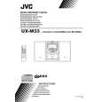 $4.99 UX-M33 JVC
Owner's Manual Complete owner's manual in digital format. The manual will be available for download as PDF file aft…
|
|
|
> |
|