|
|
|
Categories
|
|
Information
|
|
Featured Product
|
|
|
 |
|
|
There are currently no product reviews.
 ;
The content of the manual was not found on the Internet and was a hard find. I check the net for 5 hours until I came across this web-site. When I did find the book it Auto loaded into my IPAD PDF shelf for books for review at anytime. Overall I am satisfied with the book and it answered all my questions. This repair book is obsolete because the product I bout it for is pretty old. Thanks for the help with the download and even having the manual. Thanks 73's K5HRD
;
Excellent manual including schematics. The service was great and the manual helped complete the job.
;
It was magic after so many years to still be able to source this info. It was equally amazing to return my Pioneer receiver to it near new sound quality AFTER NEARLY 30 YEARS! Thank you for this ability!
;
Very quick and easy website to use and fast download of manual, quality of manual is excellent and will be pleased to use this service again in the future, thanks so much!
 ;
Easy and secure way to get a complete service manual of a vintage hifi component. Only some parts of the print copy are dificult to read. Nice price!
UX-M5R
Removing the power board (See Figs. 16 and 17.)
Remove the left and right side panels. 1. Disconnect the wires from the connector CN901 on the power board. 2. Remove the tie bands bundling the wires. 3. Remove the screw M retaining the lug wire. 4. Remove the two screws N retaining the chassis . 5. Remove the power board by pinching the two studs retaining the power board using radio pliers, etc.
Chassis Lug wire Main board
Power transformer
Stud
CN901 Stud Tie bands
N
Fig.16
M
Power board
Radio pliers, etc.
Power board Stud
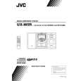
Removing the main board (See Figs. 18 and 19.)
Fig.17 Remove the left and right side panels. Remove the top cover. Remove the front panel assembly. Remove the CD mechanism assembly. 1. From the inside of the rear panel, remove the five screws P retaining the bracket. 2. Remove the two screws Q retaining the speaker terminal of the main board. 3. Remove the solder from the soldered part e that attaches the FM antenna wire to the antenna board. 4. Remove the three screws R retaining the rear panel, then remove the rear panel. 5. From the top side of the main body, remove the screw S retaining the bracket of the main board. 6. Remove the screw T retaining the regulator IC(IC302). 7. Remove the tie bands bundling the wires. 8. Disconnect the wire from the connector CN901 on the power board. 9. Remove the stud on the main board, and then take out the main board from the chassis.
Soldered part e Heat sink
Chassis
P
P
R Q
Fig.18
R
Regulator IC Main board FM antenna wire (IC302) Antenna board T Stud
CN901
S
Power board Bracket Power transformer Tie bands
Chassis
Fig.19
1-10
 $4.99 UX-M5R JVC
Owner's Manual Complete owner's manual in digital format. The manual will be available for download as PDF file aft…
|
|
|
> |
|