;
Service manual very complete and clear. It was very helpfull for my work.
;
I recently purchased a manual for a Samsung DLP tv to help with a trouble shooting problem I was having. Every tv repair shop wanted close to $400.00 for the fix, but after I found Owner-Manuals.com I hit pay dirt. The manual they had for me to purchase and download was a complete service manual for the exact tv I needed. It was complete with wiring diagrams, schematics, and even part numbers. If your the fix it yourself type I highly recommend trying to find any manual here before paying someone else to fix whatever problem your having.
;
Once again, excellent price and manual delivered in a timely manner and as advertised!
;
Outstanding quality manual. This is the exact documentation I needed to service my AKAI GX-210D. This is a PERFECT COPY of the service manual for my machine. Outstanding service. Thank-you!
;
This service manual have great value... Recommended A+++++++
;
This service manual have great value... Recommended A+++++++
UX-P3R
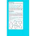
Removing the main board / heat sink (See Fig.13 to 15)
Prior to performing the following procedure, remove the metal cover, the rear cover, the CD mechanism assembly and the rear panel. 1. Disconnect the card wire from connector CN900, CN901 and CN931 on the main board. Disconnect the wire from CN906 and FW903 respectively. 2. Disconnect the wire from W950 on the underside of the main board.
CN931 CN901 CN900 Main board
CN906
FW906
Fig.13 3. Remove the two screws I attaching the main board to the chassis on the left side ofthe body and disengage the two joints c. 4. Remove the two screws J attaching the heat sink to the main board.
Front panel assembly
Main board
I
Joints c
I
Fig.14
Main board Heat sink
J
Fig.15
1-10
 $4.99 UXP3R JVC
Owner's Manual Complete owner's manual in digital format. The manual will be available for download as PDF file aft…
|