|
|
|
Categories
|
|
Information
|
|
Featured Product
|
|
|
 |
|
|
There are currently no product reviews.
 ;
Excellent printing quality.
A complete and very usefull service manual with all details.
GREAT SERVICE AT VERY LOW PRICE!
A++
;
Excellent printing quality.
A complete and very usefull service manual with all details.
GREAT SERVICE AT VERY LOW PRICE!
A++
;
Excellent printing quality.
A complete and very usefull service manual with all details.
GREAT SERVICE AT VERY LOW PRICE!
A++
;
Excellent printing quality.
A complete and very usefull service manual with all details.
GREAT SERVICE AT VERY LOW PRICE!
A++
;
Excellent printing quality.
A complete and very usefull service manual with all details.
GREAT SERVICE AT VERY LOW PRICE!
A++
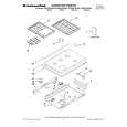
UX-P7
Removing the tuner board (See Fig.4 and 5)
Prior to performing the following procedure, remove the metal cover. 1. Disconnect the card wire from connector CN1 on the tuner board. 2. Remove the screw D on the right side of the body. 3. Remove the two screws E on the rear panel.
D
CN1 board
Fig.4
Removing the CD mechanism assembly (See Fig.6 to 8)
Prior to performing the following procedure, remove the metal cover and the rear cover. 1. Disconnect the card wires from connector CN903, CN904 and the wire from CN905 on the main board on the upper side of the body. 2. Remove the screw D attaching the tuner board and the CD mechanism on the right side of the body. 3. Remove the two screws F attaching the rear panel and the CD mechanism on the back of the body. 4. Move the rear part of the CD mechanism assembly upwards to disengage the two joints a and release from the rear panel. Pull the front panel toward the front and move the rear part of the CD mechanism assembly upwards. Then pull out the CD mechanism assembly from the front panel backward. REFERENCE: To remove the CD mechanism assembly efficiently, disconnect the card wire connecting the tuner board with the main board in advance.
E
Rear cover Rear panel
Fig.5
Rear panel Main board CN905 Tuner board
CN904 Card wires CN903
Front panel assembly
CD mechanism assembly
Fig.6
CD mechanism assembly
D
Tuner board
Fig.7
1-8
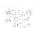 $4.99 UX-P7 JVC
Circuit Diagrams Set of circuit diagrams. The diagrams will be provided as PDF file. The file will be delivered after… 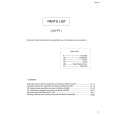 $4.99 UX-P7 JVC
Parts Catalog Parts Catalog only. It's available in PDF format. Useful, if Your equipment is broken and You need t…
|
|
|
> |
|