|
|
|
Categories
|
|
Information
|
|
Featured Product
|
|
|
 |
|
|
There are currently no product reviews.
 ;
Fast delivery and good quality copy. To be recommended
;
Excellent product, very clear print. Detailed circuit and assembly diagrams - this enabled me to repair my CD player with confidence. I highly recommend this site.
;
Fast access, 100% correct and complete service manual
;
just what i was seeking .had a password issue but the review allowed me to circumvent and download was great
;
Great manual, great price. Has a few of the basic operating instructions that most service manuals leave out. Complete instructions for disassembling board by board, safety precautions, schematics, complete parts list.
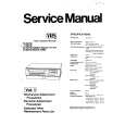
UX-V10GN
<<Cassette Mechanism Section>>
Removing the Playback/Recording & Eraser Head ( See Figs. 1 and 2 )
Cassette mechanism
1. While shifting the trigger arms seen on the right side of the head mount in the arrow direction, turn the flywheel R in counterclockwise direction Flywheel R until the head mount has gone out with a click (See Fig. 1). 2. When the flywheel R is rotated in counterclockwise direction, the Playback/Recording & Eraser head will be turned in counterclockwise direction from the position in Fig. 2 to that in Fig. 3. 3. At this position, disconnect the flexible P.C. board (outgoing from the Playback/Recording & Eraser head) Head mount Trigger arm from the connector CN31 on the head amplifier & Fig. 1 mechanism control P.C. board. 4. After dismounting the FPC holder, remove the flexible Playback/Recording & P.C. board. eraser hyead Spring "a" 5. Remove the flexible P.C. board from the chassis base. Frexible 6. Remove the spring Afro behind the Playback/Recording board Trigger arm & Eraser head. 7. Loosen the reversing azimuth screw retaining the Playback /Recording & Eraser head. 8. Take out the Playback/Recording & Eraser head from the front of the head mount. 9. The Playback/Recoring & Eraser head should also be removed similarly according to Steps 1 ~ 8 above. Head amplifier & mechanism control P.C. board Reassembling the Playback/Recording & Eraser Head 1. Reassemble the playback head from the front of the head mount to the position as shown in Fig. 3. 2. Fix the reversing azimuth screw. 3. Set the spring "a" from behind the Playback/Recording & Eraser head. 4. Attach the flexible P.C. board to the chassis base, and fix it with the FPC holder as shown in Fig. 3. 5. The Playback/Recording & Eraser head should also be reassembled similarly to Step 1 ~ 4 above. Fig. 2 Playback/Recording & eraser head Reversing azimuth screw Flywheel R
Spring "a"
Head mount Frexible board
FPC holder Fig. 3
Head amplifier & mechanis control P.C. board
1-12
|
|
|
> |
|