|
|
|
Categories
|
|
Information
|
|
Featured Product
|
|
|
 |
|
|
There are currently no product reviews.
 ;
Excellent printing quality.
A complete and very usefull service manual with all details.
GREAT SERVICE AT VERY LOW PRICE!
A+++++++++++++++++++++++++
;
Thank you for providing quickly a manual so old! very good job clear and understandable!
;
Excellent printing quality.
A complete and very usefull service manual with all details.
GREAT SERVICE AT VERY LOW PRICE!
A+++++++++++++++++++++++++
;
Excellent printing quality.
A complete and very usefull service manual with all details.
GREAT SERVICE AT VERY LOW PRICE!
A+++++++++++++++++++++++++
;
Excellent printing quality.
A complete and very usefull service manual with all details.
GREAT SERVICE AT VERY LOW PRICE!
A+++++++++++++++++++++++++
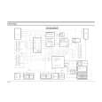
Alignment and Adjustment
5-3 Head Switching Point Adjustment
1) Playback the alignment tape. 2) Press the �SW703� button on Main PCB with pincers to set the adjustment mode. (See Fig. 5-2 ) 3) Press the �SP/LP� button of remote control then adjustment is operated automatically. (See Fig. 5-1) 4) Turn the Power off.
5-4 NVRAM Option Setting
1) NVRAM Option is adjusted at production line basically. 2) In case Micom (IC601) and NVRAM (IC605 ; EEPROM) is replaced, be sure to set the corresponding ooption number of the repaired model. (If the option is not set, the unit is not operated.) 1) Press the �SW703� button on Main PCB to set the adjustment mode. (See Fig. 5-2) 2) Press the �MENU� button on the remote control about 5 seconds then option setting display is appeared. (See Fig. 5-14) 3) Select the option number (See Table 5-2) of corresponding model with �CURSOR� button on the remote control. 4) If selecting the option number is completed, press the �OK� button of remote control. (If �OK� button is pressed, the selected number is changes reversed color. ; See Fig. 5-14) 5) Press the �MENU� button of remote control again to store the option number. (�PLEASE WAIT� is displayed for a second as shown Fig. 5-15 and this setting is completed.) 6) Turn the Power off.
01 09 17 25 33 41 49 57 65
02 10 18 26 34 42 50 58 66
03 04 05 06 07 08 11 12 13 14 15 16 19 20 21 22 23 24 27 28 29 30 31 32 35 36 37 38 39 40 43 44 45 46 47 48 51 52 53 54 55 56 59 60 61 62 63 64 67 68 69 70 71 72 CNG : OK SAVE : MENU
Fig. 5-14 <Table 5-2>
01 09 17 25 33 41 49 57 65
02 10 18 26 34 42 50 58 66
03 04 05 06 11 12 13 14 19 20 21 22 27 28 29 30 35 36 37 38 43 44 45 46 51 52 53 54 59 60 61 62 67 68 69 70 PLEASE WAIT
Fig. 5-15
07 15 23 31 39 47 55 63 71
08 16 24 32 40 48 56 64 72
MODEL V-621UK
OPTION NUMBER 4, 5, 6, 8, 9, 10, 11, 14, 18, 25, 26, 29, 30, 33, 38, 40, 41, 46, 49, 50, 53, 60, 61, 64
5-8
Toshiba
|
|
|
> |
|