|
There are currently no product reviews.
 ;
muy buen manual con multiples graficos y formas de onda ademas de muy completo y bien presentado.
 ;
As Always these people were very rapid and efficient. A great job helping hobbiest and workers!!! Thank you a lot!
;
Excellent printing quality.
A complete and very usefull service manual with all details.
GREAT SERVICE AT VERY LOW PRICE!
A+++++++++++++++++++++++++
;
Excellent printing quality.
A complete and very usefull service manual with all details.
GREAT SERVICE AT VERY LOW PRICE!
A+++++++++++++++++++++++++
;
Thank you for providing quickly a manual so old! very good job clear and understandable!
INC
VAA12201-R.3581.A
14. SB UNIT
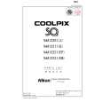
â� Attach the SB flash unit ã�» Pass the red and white wires of the main condenser through the space between the pillar A and the wall of the joint unit. ï¼�ref. Fig.1ï¼� ã�» Put the yellow wire of the trigger around the outside of the pillar A, and assemble the flash unit. ï¼�ref. Fig.2ï¼� ã�» Attach 2 screws (#802). Noteï¼�In case of using a tweezer when arranging each wire (red, white and yellow) of the SB unit, be careful not to damage the cable sheath. ï¼�If using a sharp-edged tweezer, cover it with the constriction tube, etc. )
Pillar A of the joint unit
White �Red
Arrangement of red and white wires Fig.1
#802�2
Yellow
SB flash unit
Pillar A
Put the yellow wire around the outside of the pillar A Fig.2
�Attach the red and white wires of the main condenser to the both-sided adhesive tape that is attached on the lens-barrel. �ref. Fig.3� Both-sided adhesive tape
(#567)
�Note�Do not slacken the red and white wires, and do not allow them to put on the corner of the joint unit.
Corner of the joint unit Fig.3
- A17 ï½¥ SQ -
|