|
|
|
Categories
|
|
Information
|
|
Featured Product
|
|
|
 |
|
|
There are currently no product reviews.
 ;
It's the manual, I am searching for. Now I am able to repair my Braun A501.
 ;
Great service manual. Unfortunately on page no. 41 there are some details which i can't read.
;
Wonderful service... doubt that I could have made the repairs to my turntable without this service manual. Great help!
Well worth the price paid!
;
nice completed SERVICE MANUAL as the description THANK YOU !!!-
;
The service manual is as described and received the link to the download sooner than expected. Great service, quality product. This site is a big help in the electronics repair business.
VC-A300X/NZ VC-A550X
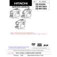
INSTALLING THE MASTER CAM (AT REAR SIDE OF MECHANISM CHASSIS)
1. Make sure beforehand that the shifter is at the point as shown below. 2. Place the master cam in the position as shown below.
REPLACEMENT OF LOADING MOTOR
� Removal
E ring (XRESJ30-06000) Master cam Apply grease Apply grease
Fully turn clockwise
Fully turn counterclockwise Face the wide tooth side ward No grease
Figure 4-44-1.
Note: See the figure below for the phase matching between the master cam and the casecon drive gear. 3. Finally fix with the E ring.
Master cam
Figure 4-45.
Casecon drive gear
Half-round notch Round mark
� Replacement Remove the loading motor, and install the replacement loading motor as shown below.
10.2 +0.2 mm �0.2
When installing the master cam, align the casecon drive gear round mark with the half-round notch of master cam.
Figure 4-44-2.
Figure 4-46. The loading motor pressing-in must be less than 147 N (15 kgf). Adjust the distance between motor and pulley to 10.2 +0.2 mm).
�0.2
27
|
|
|
> |
|