|
|
|
Categories
|
|
Information
|
|
Featured Product
|
|
|
 |
|
|
There are currently no product reviews.
 ;
Quick site processing. A complete and very useful manual with all details. Thank you!
;
Quick service response. A useful and very rare service manual with all details. I recomend this service.
;
I ordered this manual sometime in the afternoon and I received it on my e-mail the same evening.
This is a fantastically good and properly scanned copy of the original manual. All pages are of the same scale and they overlap each other. It means that you can print the manual and easily make it as a convenient paper manual.
The content of the manual is fantastic. Alignment descriptions, PCB layouts and elementary diagrams are explicit and precise. I immediately found what I was looking for. Thanks to this manual and Owner-Manuals.com my amplifier is alive again. Many thanx indded!
;
The manual was well-scanned and easy to read. As an added bonus, the Operator's Manual was bundled with the Service Manual!
I'd definitely use owner-manuals.com again.
;
Finally, i found one website, where i can download this service manual , and fix my hifi. The service manual is very good, and easy to download and to print.
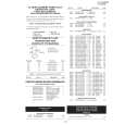
VC-FH3GM/SM VC-FH5GM
INSTALLING THE MASTER CAM (AT REAR SIDE OF MECHANISM CHASSIS)
1. Make sure beforehand that the shifter is at the point as shown below. 2. Place the master cam in the position as shown below.
REPLACEMENT OF LOADING MOTOR
� Removal
E ring (XRESJ30-06000) Master cam Apply grease Apply grease
Fully turn clockwise
Fully turn counterclockwise Face the wide tooth side ward No grease
Figure 4-44-1.
Note: See the figure below for the phase matching between the master cam and the casecon drive gear. 3. Finally fix with the E ring.
Master cam
Figure 4-45.
Casecon drive gear
Half-round notch Round mark
� Replacement Remove the loading motor, and install the replacement loading motor as shown below.
10.2 +0.2 mm �0.2
When installing the master cam, align the casecon drive gear round mark with the half-round notch of master cam.
Figure 4-44-2.
Figure 4-46. The loading motor pressing-in must be less than 147 N (15 kgf). Adjust the distance between motor and pulley to 10.2 +0.2 mm).
�0.2
26
|
|
|
> |
|