|
|
|
Categories
|
|
Information
|
|
Featured Product
|
|
|
 |
|
|
There are currently no product reviews.
 ;
Tartalma megfelelő. Szebb kivitelű is lehetne a scannelés.
 ;
I never been disappointed in my dealings with owners-manuals.com
;
Excellent printing quality. A complete and very useful manual with all details.
;
Even if the PDF is a scan, I can read the information I need.
The price is affordable and the service (mail sending) is very fast.
Thanks ! Regards. William (Fan of Kenwood)
;
Very good quality original datasheet!I like this amazing website!!!!!!
VC-H700X
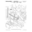
INSTALLING THE MASTER CAM (AT REAR SIDE OF MECHANISM CHASSIS)
1. Make sure beforehand that the shifter is at the point as shown below. 2. Place the master cam in the position as shown below.
REPLACEMENT OF LOADING MOTOR
� Removal
E ring (XRESJ30-06000) Master cam Apply grease Apply grease
Fully turn clockwise
Fully turn counterclockwise Face the wide tooth side ward No grease
Figure 4-44-1.
Note: See the figure below for the phase matching between the master cam and the casecon drive gear. 3. Finally fix with the E ring.
Master cam
Figure 4-45.
Casecon drive gear
Half-round notch Round mark
� Replacement Remove the loading motor, and install the replacement loading motor as shown below.
10.2 +0.2 mm �0.2
When installing the master cam, align the casecon drive gear round mark with the half-round notch of master cam.
Figure 4-44-2.
Figure 4-46. The loading motor pressing-in must be less than 147 N (15 kgf). Adjust the distance between motor and pulley to 10.2 +0.2 mm).
�0.2
26
|
|
|
> |
|