|
|
|
Categories
|
|
Information
|
|
Featured Product
|
|
|
 |
|
|
There are currently no product reviews.
 ;
y'm hapy for this shoping . Estoy feliz por esta compra , ahora puedo reparar mi equipo de audio que AMO . And very good price for this manual . Thank yuo .
;
Perfect manual, perfect service. Easy reading. Thanks a lot
;
Very good quality download here. Great hard to find manuals at a reasonable price.
 ;
I had a problem with the mains transformer, I did not know the voltages on the secondary, this manual helped me to solve this problem, thanks for the manual!
;
Great manual, great quality copy, complete parts reference and scematics, Thank you
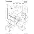
VC-M522HM VC-MH722HM VC-MH732HM
INSTALLING THE MASTER CAM (AT REAR SIDE OF MECHANISM CHASSIS)
1. Make sure beforehand that the shifter is at the point as shown below. 2. Place the master cam in the position as shown below.
REPLACEMENT OF LOADING MOTOR
� Removal
E ring (XRESJ30-06000) Master cam Apply grease Apply grease
Fully turn clockwise
Fully turn counterclockwise Face the wide tooth side ward No grease
Figure 4-44-1.
Note: See the figure below for the phase matching between the master cam and the casecon drive gear. 3. Finally fix with the E ring.
Master cam
Figure 4-45.
Casecon drive gear
Half-round notch Round mark
� Replacement Remove the loading motor, and install the replacement loading motor as shown below.
10.2 +0.2 mm �0.2
When installing the master cam, align the casecon drive gear round mark with the half-round notch of master cam.
Figure 4-44-2.
Figure 4-46. The loading motor pressing-in must be less than 147 N (15 kgf). Adjust the distance between motor and pulley to 10.2 +0.2 mm).
�0.2
26
|
|
|
> |
|