|
There are currently no product reviews.
 ;
This is a very good quality print (scan) of the original SONY service manual. The original from Sony is on very thin paper. Nevertheless it is very clear and sharp and excellent readable. I'm very satisfied to have now this rare document. I've looking for it many years (infrequent). It contains very detailed circuit diagrams, exploded views, part lists, PCB view with good readable connection lines. Very recommended.
;
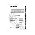
A complete manual with all the needed details of calibrations and service instructions about the radio receiver.
A big deal.
Many thanks !
;
Fast delivery and good quality copy. To be recommended
;
Excellent product, very clear print. Detailed circuit and assembly diagrams - this enabled me to repair my CD player with confidence. I highly recommend this site.
;
Fast access, 100% correct and complete service manual
SAFETY NOTES: 1. DISCONNECT THE AC PLUG FROM THE AC OUTLET BEFORE REPLACING PARTS. 2. SEMICONDUCTOR HEAT SINKS SHOULD BE REGARDED AS POTENTIAL SHOCK HAZARDS WHEN THE CHASSIS IS OPERATING.
NOTE:
1. 2. 3. 4. The unit of resistance "ohm" is omitted (K = 1000 ohms and M = 1 Mega ohm). All resistors are 1/8 watt, unless otherwise stated. The unit capacitance "F" is omitted ( µ = µF, p = pF). The values in parentheses are the ones in the PB mode, the values without parentheses are the ones in the REC mode.
VOLTAGE MEASUREMENT CONDITIONS: 1. DC voltages are measured between points indicated and chassis ground by VTVM, with AC230V/50Hz supplied to unit and all controls are set to normal viewing picture unless otherwise stated. 2. Voltages are measured with 10000µV B & W or colour signal. WAVEFORM MEASUREMENT CONDITIONS: 10000dBµV 87.5 percent modulated colour bar signal is fed into tuner.
1
2
3
4
5
6
7
8
9
10
13
|