|
|
|
Categories
|
|
Information
|
|
Featured Product
|
|
|
 |
|
|
There are currently no product reviews.
 ;
I thank Owner-Manuals.com for providing the necessary manual very quickly, and it was very helpful in repairing my personal Audio System and I once again thank them for the wonderful customer's service satisfaction.
Thanks.
;
Everything fine: quick service, no glitch and above all a very good quality of the Pdf file. Thank you!
;
The manual was complete, parts list, adjustment procedures, etc. No worries
 ;
Very usefully, I could find the trouble clearly with that manual.
;
Bon produit. Permet de corriger les couleurs et de redonnez un petit coup de jeune à vos vieilles vidéos. On regrettera juste le manque d'une prise s-vidéo.
5. A/C HEAD HORIZONTAL POSITION ADJUSTMENT
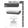
Purpose: To adjust the Horizontal Position of the A/C Head. Symptom of Misadjustment: If the Horizontal Position of the A/C Head is not properly adjusted, a maximum envelope cannot be obtained at the Neutral Position of the Tracking Control Circuit. Place a jumper between TP6003 on the Video Signal Process Section and +5V(TP6009) on the System Control Section of the Main C.B.A. to defeat Auto Tracking. 1. Eject the tape and insert it again to access the Neutral Tracking position. Connect the oscilloscope to TP3002 on the Video Signal Process Section of the Main C.B.A. Use TP6205 as a trigger. 2. Play back the alignment tape and confirm that the RF envelope appears. 3. If adjustment is required, loosen the Black Screw (D) and tighten it lightly. Set the H-Position Adjustment Driver into the Hole (A). Then slowly turn the fixture either clockwise or counterclockwise so that the envelope is at maximum. 4. Before finding the center of the maximum period of the envelope, rotate the fixture back and forth slightly to confirm the limits on either side of the maximum period. 5. Push the Tracking Control Up Button (on the Remote Control) several times (count the number of times pushed) until the maximum envelope is reduced to 1/2. 6. Reset the tracking to the neutral position by ejecting the tape and reinserting it. Push the Tracking Control Down Button (on the Remote Control) several times (count the number of times pushed) until the maximum envelope is reduced to 1/2. 7. If the number of pushing is not the same, then loosen the Black Screw (D) and set the H-Position Adjustment Driver into the Hole (A) to find the center point. Then repeat the above procedure to determine the center point. 8. Tighten Black Screw (D). 9. Remove the jumper between TP6003 and +5V(TP6009).
Black Screw (D)
Hole (A)
Fig. M11 Note: Old type of H-Position Adjustment Driver (VFK0136) can be used for this adjustment.
2-23
|
|
|
> |
|