|
|
|
Categories
|
|
Information
|
|
Featured Product
|
|
|
 |
|
|
There are currently no product reviews.
 ;
OEM manual provided all schematics, board layouts and component specs necessary to facilitate unit maintenance. All pages were clear and readable.
;
Good condition and quality. Hard to find anywhere in Internet, only on this site.
 ;
Exactly what I needed to be able to bring the amp back to life... will come back to this site the next time I need schematics.
;
Information was accurate and very helpful.
However the continuity made it a little difficult to follow from one page to the next.
;
Very very good as usual very trustable site. Perfect!!!!!!
VL-H870U VL-H875U VL-H890U
VL-H870U VL-H875U VL-H890U
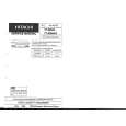
4-2. REMOVAL OF THE CAMERA PARTS
Note: Before removing the Cabinet, turn off the power supply,and ascertain that the battery has been removed.
(b) (d) (c) (c)
(a)
(c)
(b) Pull out (d) Pull out Camera front cabinet
1. Remove the screws (b)LX-HZ0018TAFF(1pc.),(a)LX-HZ 0018TAFN(1pc.),(c)LX-HZ0045TAFN(1pc.)and (d)XiPSF20P04000(1pc.), pull out the Front cabinet.
Speaker connector
(g) Camera rear grip cover
Remove
4. Remove the screws(b)LX-HZ0018TAFF(1pc.),(c)LXHZ0045TAFN(2pcs.)and (d)XiPSF20P04000(1pc.),pulling out the Camera rear Cabinet, and remove the Speaker connector.
(c)
(g)
2. Remove the screws (g)LX-HZ0045TAFF(2pcs.) and the Camera rear grip cover .
Battery catcher connector Pull out
Connector
Tilt Frame C
Claw
3. Remove the connector.
5. Remove the screw(c)LX-HZ0045TAFN(1pc.)and pull out the Tilt Frame C. Pull out the Tilt Frame C. at right angle, because of closing the claw. Then, pull out the battery catcher connector from the Tilt Frame C.
4-4
|
|
|
> |
|