|
|
|
Categories
|
|
Information
|
|
Featured Product
|
|
|
 |
|
|
There are currently no product reviews.
 ;
This is a high quality manual with clear schematic and components layout diagrams ; with service procedure included.
 ;
This service manual for the Kenwood KT-990D was reproduced really well ,is very legible and manual is complete.Combined with the low price paid,in the future,I will be checking Owner-Manuals.com any time I need a manual.
;
When I purchased this manual I had my doubts regarding the quality as the price was so reasonable as compared to other outlets.
The manual itself is of high standard the print is very clear as are the diagrams. Obviously with the diagrams one has to zoom in otherwise it is to small to be able to read.
Overall I am very pleased with the company who delivered as they said and with the manual they supplied.
I occasionally require a manual and now having registered with this company I shall order from them in the future.
;
I was at first dubious about payiong for downloaded manuals but having done so, I was extremely impressed with quality of the two manual I ordered, well worth the small price I paid.
I would highly recommend these to my friends.
;
reasonable price for the schematic - the service is perfect, all as expected and pointed by instructions - good scan of the original plans - thank you!
VL-ME100S/H/E
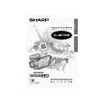
3. DISASSEMBLY OF THE SET
Note: Before removing the cabinet, turn off the power supply, and ascertain that the battery have been removed. 1. 2.
Note: After the cabinet B is inserted between the zoom unit and the ANG, it is secured with screw. If the cabinet B is secured with screw with it inserted between the cabinet A and the zoom unit, the zoom does not operate.
Screw Cabinet A Zoom unit Cabinet B
LCD monitor lock release button
(e) (f) (b) Terminal side cabinet
ANG
A
(o) Cabinet A (b) LCD monitor release button Shoe cover (b) Shoe metal cover
� Remove the screw ((o)XiPSF17P05000)(1 pc.) fixing the cabinet A. � Remove the screw ((b)XiPSF17P03000)(1 pc.) to remove the � Press the LCD monitor lock release button and open the LCD shoe metal cover. by 90�. � Remove the screws ((f)XiPSN17P04000)(1 pc.), ((e) � While pulling up the LCD monitor release button, slide the LCD XiPSN17P03000)(2 pcs.) and ((b) XiPSF17P03000)(1 pc.) in the horizontal direction and lift it to remove it. (Shift the LCD fixing the terminal side cabinet. in the direction indicated by the arrow A.) � Remove the screw ((b)XiPSF17P03000)(1 pc.) fixing the shoe cover.
3.
Viewfinder
(b)
(e) (b) (d) (f)
Battery cover Cabinet B
(f)
� Remove the screws ((e)XiPSN17P03000)(3 pcs.), ((f)XiPSN17P04000)(3 pcs.) and ((d)XiPSN17P02000)(1 pc.) fixing the cabinet B. � Remove the screws ((b) XiPSF17P03000)(6 pcs.) fixing the battery cover to remove the cabinet B, and then remove the battery cover. (Since the main PWB 1, the battery cover FPC, the viewfinder FPC, and the cabinet B FPC are connected, remove the FPC connector.) � Remove the viewfinder from the battery cover. (They are engaged by claws.) � Remove the shoe cover. (They are engaged by claws.) (Since the main PWB 1 and the hot shoe FPC are connected, remove the FPC connector.)
4
|
|
|
> |
|