|
|
|
Categories
|
|
Information
|
|
Featured Product
|
|
|
 |
|
|
There are currently no product reviews.
 ;
About one hour after checkout, the manual was available for download. Clear reading and detailed. Thanks
;
Excellent transaction - clean document received - Thanks a lot
;
Manual is in German but complete. I needed this one to fix a long lasting problem with the internal PSU of the camera. Most of the capacitors begin to leak after a few years wich results in the inability to power on the camera. When you try to turn it on the power led flickers and the unit directly turns off. Thanks to this manual I was able to locate all bad cap's and to dis- and reassemble the camera without any problems.
 ;
We received the manual in a timely manner and it was exactly what we were expecting.
;
Excellant, finally this is want I need and searching for The service manual is fantastic and thank you to owner-manuals.com and its service. Price is reasonable. It's a bit slow on my end in downloading but manage to receive the whole manual without a break. once again, thanks.
VL-PD5S/E
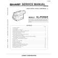
8-3. How to operate with the circuit board without the cassette controller assembly.
In this method, if the procedure is followed incorrectly there is danger of damaging the mechanism and the tape, so except in special cases, such as when measuring the VSR torque, do not perform this procedure. Normally operate this unit with the cassette controller assembly attached. Be sure to follow each caution mentioned. (1) Apply DC3V to the loading motor to set the EJECT mode. (2) Remove the down switch angle. 1) In Fig. 5 remove the screws P and Q . Note) The loading motor solder joint (part T, Fig. 5) of DEW sensor FPC applied to the down switch angle is not removed. After the down switch angle is removed, take care so that the DEW sensor FPC is not broken. (3) Surely secure the moving piece R of down switch as shown in Fig. 6 with the aid of adhesive tape so that the switch is turned on. (4) Install the down switch angle. Note) To set the REC mode, press the pin of recognition switch S (not required in other modes). (5) Set the test mode (T-01) with the adjustment remote controller without loading the tape. Thereby the mechanism operation is enabled with the mode key. (6) To eject, remove the tape (3).
T
P
Q
S
8-4. Phase matching
For the parts listed below, match the phases as shown in Fig. 7. (1) AHC cam (2) MODE switch (3) Main cam (4) Sub cam Note) Before disassembling, check the marker positions carefully. Note) When installing the engagement gear, make sure that the main cam and sub cam phase matching hole aligns with the chassis hole. Note) After phase matching, turn the MODE switch by hand and confirm that it turns almost one complete turn. (After checking, return it to its original position.)
Fig. 5. STANDBY mode
R Down switch moving piece
R Down switch moving piece Down switch angle
Adhesive tape Adhesive tape
AHC cam Phase matching hole (for chassis) Phase matching mark
Fig. 6
MODE switch
Phase matching mark
Main cam
Coupling gear
Sub cam Phase matching hole (for chassis)
Phase matching hole (for chassis)
Fig. 7
15
 $4.99 VL-PD5E SHARP
Parts Catalog Parts Catalog only. It's available in PDF format. Useful, if Your equipment is broken and You need t…
|
|
|
> |
|