|
|
|
Categories
|
|
Information
|
|
Featured Product
|
|
|
 |
|
|
There are currently no product reviews.
 ;
I am very happy regarding the online purchase of this manual from Owner-Manuals.com as with this I could set right my Denon CD player and Amplifier.
I once again sincerely thank them for the prompt service which was rendered to me.
N. Shanker
;
More than pleased with my prurchase, very good product for the price.
;
Manual-link came 30 minutes after having paid for an extremely rare (40 years old) item (sony icr-120) and helped me to get the radio rework again. So really good help for me, fast and reliable delivery and -taken that into consideration- a very reasonable price for that service. So thanks again! Mike, Germany
 ;
Some of the pictures in this manual are a bit irritating. I had to dissassemble the unit and some of the screws have different threads, which is not mentioned in this manual. Also some of the drawings of the boards look different than the actual boards.
After all, the manual was very useful. I was able to recalibrate the capstan drive and it is working fine again.
;
This manual is very good. 303 pages scanned in a very high resolution. My camera has bad, leaking capacitors which all of the V5000 models are suffering from these days.
There is a huge part list with all capacitors, transistors etc. in this manual which helped me a lot. Otherwise I would not have been able to buy replacement parts.
The dissassembly guide is very enormous and detailed. Unlike on the Panasonic MS1 manual I downloaded here it actually looks like the real parts look. And the screws are labeled correctly, so you shouldn't have any left after the repair. ;)
VL-PD5S/E
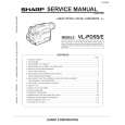
8-3. How to operate with the circuit board without the cassette controller assembly.
In this method, if the procedure is followed incorrectly there is danger of damaging the mechanism and the tape, so except in special cases, such as when measuring the VSR torque, do not perform this procedure. Normally operate this unit with the cassette controller assembly attached. Be sure to follow each caution mentioned. (1) Apply DC3V to the loading motor to set the EJECT mode. (2) Remove the down switch angle. 1) In Fig. 5 remove the screws P and Q . Note) The loading motor solder joint (part T, Fig. 5) of DEW sensor FPC applied to the down switch angle is not removed. After the down switch angle is removed, take care so that the DEW sensor FPC is not broken. (3) Surely secure the moving piece R of down switch as shown in Fig. 6 with the aid of adhesive tape so that the switch is turned on. (4) Install the down switch angle. Note) To set the REC mode, press the pin of recognition switch S (not required in other modes). (5) Set the test mode (T-01) with the adjustment remote controller without loading the tape. Thereby the mechanism operation is enabled with the mode key. (6) To eject, remove the tape (3).
T
P
Q
S
8-4. Phase matching
For the parts listed below, match the phases as shown in Fig. 7. (1) AHC cam (2) MODE switch (3) Main cam (4) Sub cam Note) Before disassembling, check the marker positions carefully. Note) When installing the engagement gear, make sure that the main cam and sub cam phase matching hole aligns with the chassis hole. Note) After phase matching, turn the MODE switch by hand and confirm that it turns almost one complete turn. (After checking, return it to its original position.)
Fig. 5. STANDBY mode
R Down switch moving piece
R Down switch moving piece Down switch angle
Adhesive tape Adhesive tape
AHC cam Phase matching hole (for chassis) Phase matching mark
Fig. 6
MODE switch
Phase matching mark
Main cam
Coupling gear
Sub cam Phase matching hole (for chassis)
Phase matching hole (for chassis)
Fig. 7
15
 $4.99 VL-PD5S SHARP
Parts Catalog Parts Catalog only. It's available in PDF format. Useful, if Your equipment is broken and You need t…
|
|
|
> |
|