|
|
|
Categories
|
|
Information
|
|
Featured Product
|
|
|
 |
|
|
There are currently no product reviews.
 ;
again you did a very good job. It was fast too. Photocopy are really readable and clear
 ;
Probably it never existed a 1081 official service manual from Commodore, it's look more like a NAPCEC service manual & diagrams compilation of the 1084 series and his variants, like the nap6523, 8cm505, 1084S, 1084P and obviously the 1081. It's more complete than other scans and the quality of the scans also are far superior. It has two circuit diagrams variants of the 1081, mono and stereo versions. It doesn't include a diagram for the Philips CM8500 or CM8501, they look like the 1081 but they are slightly different.
;
Rapid, clear well done as all the scheme I downloaded from this site. Great job very functional and very useful
;
Great copy of the manual, has all information required for servicing,
;
I work at an authorized service center and I can tell if a manual is as it should be. This one is. It may be a scan, but a very good one at that. The interesting part for me was the curcuit diagram which was scanned at high quality, making it as good as the original. I will definitely be back as a customer. I need not say this, but I will: the price was the best. Thank you owner-manuals.com .
VL-PD6S/H/E
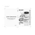
3. DISASSEMBLY OF THE SET
Note: Before removing the cabinet, turn off the power supply, and ascertain that the battery have been removed. 1.
LCD monitor lock release button Top cover
4.
(Q)
(A)
�
Zoom microphone terminal PWB
� Press the LCD monitor lock release button, and open the LCD by 90�. � While the LCD monitor lock release lever is pulled up, move the LCD remote control horizontally and lift it up to remove it. (Move the LCD remote control in the direction of the arrow A.)
2.
� After the V/F section is pulled out and is turned, remove the three screws ((Q)XiPSN17P03000) on the shoe fitting. Then, slide the top cover and lift it up to remove it. � Remove the one screw ((A)LX-BZ0192TAFF) to remove the zoom microphone terminal PWB.
5.
V/F section
(P) (P) (R) (P)
� Remove the four screws ((P)XiPSF17P03000) on the bottom cover to remove the bottom cover. � Remove the connector of the card and the connector of the zoom unit on the bottom.
(P) (P) Battery cover
3.
(Q)
� Lift up the V/F section, and remove the four screws ((P)XiPSF17P03000), the one screw ((R)XiPSF17P04000) to remove the battery cover. � Remove the connector of the battery terminal and the connector of the power SW.
6.
(P)
(P)
(P)
(Q)
(Q) Claw Front cover (P) (G)
� Remove the three screws ((Q)XiPSN17P03000) and the two screws ((P)XiPSF17P03000) on the front cover to remove the front cover. Note:Be careful that the claw on the front cover engages with cassette lid. � Remove two sheets of FPC of the eject, zoom microphone and AV terminal unit.
� Remove the one screw ((Q)XiPSN17P03000), one screw ((G)LX-HZ0050TAFF) and open the cassette lid. Then, remove the three screws ((P)XiPSF17P03000) on the both ends and in the center. � Remove each connector of the eject switch, H/A, zoom unit, and card socket unit.
4
|
|
|
> |
|