|
|
|
Categories
|
|
Information
|
|
Featured Product
|
|
|
 |
|
|
There are currently no product reviews.
 ;
I never been disappointed in my dealings with owners-manuals.com
;
Excellent printing quality. A complete and very useful manual with all details.
;
Even if the PDF is a scan, I can read the information I need.
The price is affordable and the service (mail sending) is very fast.
Thanks ! Regards. William (Fan of Kenwood)
;
Very good quality original datasheet!I like this amazing website!!!!!!
 ;
Excellent just what I needed to replace the electrolytic caps and make this old gem a beauty again. Was as scan of the original photocopied service manual.
VL-SD20U
VL-SD20U
9-3. How to operate with the circuit board without the cassette controller assembly.
In this method, if the procedure is followed incorrectly there is danger of damaging the mechanism and the tape, so except in special cases, such as when measuring the VSR torque, do not perform this procedure. Normally operate this unit with the cassette controller assembly attached. Be sure to follow each caution mentioned. (1) Apply DC3V to the loading motor to set the EJECT mode. (2) Remove the down switch angle. 1) In Fig. 5 remove the screws P and Q . Note) The loading motor solder joint (part T, Fig. 5) of DEW sensor FPC applied to the down switch angle is not removed. After the down switch angle is removed, take care so that the DEW sensor FPC is not broken. (3) Surely secure the moving piece R of down switch as shown in Fig. 6 with the aid of adhesive tape so that the switch is turned on. (4) Install the down switch angle. Note) To set the REC mode, press the pin of recognition switch S (not required in other modes). (5) Set the test mode (T-01) with the adjustment remote controller without loading the tape. Thereby the mechanism operation is enabled with the mode key. (6) To eject, remove the tape (3).
T
P
Q
S
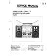
9-4. Phase matching
For the parts listed below, match the phases as shown in Fig. 7. (1) AHC cam (2) MODE switch (3) Main cam (4) Sub cam
Fig. 5. STANDBY mode
R Down switch moving piece
Note) Before disassembling, check the marker positions carefully. Note) When installing the engagement gear, make sure that the main cam and sub cam phase matching hole aligns with the chassis hole. Note) After phase matching, turn the MODE switch by hand and confirm that it turns almost one complete turn. (After checking, return it to its original position.)
Down switch angle
R Down switch moving piece
Adhesive tape Adhesive tape
AHC cam Phase matching hole (for chassis) Phase matching mark
Fig. 6
MODE switch
Phase matching mark
Main cam
Coupling gear
Sub cam Phase matching hole (for chassis)
Phase matching hole (for chassis)
Fig. 7
9-3
|
|
|
> |
|