|
|
|
Categories
|
|
Information
|
|
Featured Product
|
|
|
 |
|
|
There are currently no product reviews.
 ;
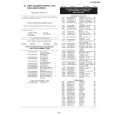
This is a very good quality print (scan) of the original SONY service manual. The original from Sony is on very thin paper. Nevertheless it is very clear and sharp and excellent readable. I'm very satisfied to have now this rare document. I've looking for it many years (infrequent). It contains very detailed circuit diagrams, exploded views, part lists, PCB view with good readable connection lines. Very recommended.
;
A complete manual with all the needed details of calibrations and service instructions about the radio receiver.
A big deal.
Many thanks !
;
Fast delivery and good quality copy. To be recommended
;
Excellent product, very clear print. Detailed circuit and assembly diagrams - this enabled me to repair my CD player with confidence. I highly recommend this site.
;
Fast access, 100% correct and complete service manual
VL-WD650S/E
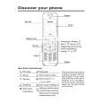
3. DISASSEMBLY OF THE SET
Note: Before removing the cabinet, turn off the power supply, and ascertain that the battery have been removed. 1.
(d)
Turn SW connector LCD FPC 1, 2
3.
(d)
(e)
Joint main FPC
(b) (d)
(b) (c)
1) Disconnect the connector of the turn SW. 2) Remove the joint main FPC. 3) Remove the LCD FPCs (2 sheets), and lift up the cabinet B ass'y.
4.
1) Remove the screws ((c)XiPSF17P04000)(5 pcs.) and ((b)LXHZ0063TAFF)(1 pc.) on the bottom cover to remove the bottom cover. 2) The screws ((d)XiPSN17P04000)(2 pcs.), ((b)LX-HZ0063TAFF)(1 pc.) and ((e)LX-HZ0063TAFN)(1 pc.) on the front cover, and open the front cover. Then disconnect the connector of the microphone. 3) Remove the screws ((d)XiPSN17P04000)(3 pcs.) fixing the shoe angle to remove the shoe angle. Remove the connector of the zoom microphone which is located in the front, and then slide the top side cover forward and lift it up to remove it.
(b)
Operation PWB connector
2.
(d)
(b) (b)
(b)
1) Remove the screws ((b)LX-HZ0063TAFF)(5 pcs.) to remove the joint PWB. 2) Disconnect the connector of the operation PWB. 3) Remove the screws ((b)LX-HZ0063TAFF)(3 pcs.) to remove the operation PWB.
(d)
5.
(d)
(c) (b)
(d)
1) Turn the V/F, and then remove the screws ((b)LX-HZ0063TAFF)(7 pcs.) and ((c)XiPSF17P04000)(1 pc.) fixing the battery cover. Disconnect the connector of the battery terminal on the bottom. 2) Remove the screws ((d)XiPSN17P04000)(4 pcs.) on the top side and the screw ((d)XiPSN17P04000)(1 pc.) on the side. 1) Disconnect the connectors (2 pcs.) of the lens, remove the screw ((d)XiPSN17P04000)(1 pc.), and lift it up. 2) Disconnect the connector of the V/F, remove the screw ((d) XiPSN17P04000)(1 pc.), and lift up the V/F unit to remove it.
4
|
|
|
> |
|