|
There are currently no product reviews.
 ;
Thank you very much you are helping me a lot with my preferred hobby!!! this manual of an old TV is going to be very helpful!!!!
You are very honest competent great job very clear and well done!!!!
Matteo
;
An excellent service manual contains dismantling locations of components, electronic adjustments,worth the money.
;
Caracteristiques,circuit adjusment,notes on schematis diagram,it's a good service manual,to live well,thanks.
;
Service Manual in good quality, with all of the pages.
;
Very usrfull for repaur, great quality copy. includes complete parts list and schematics
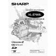
VL-Z700S-T VL-Z800S-S/E-S/E-T/Z900H-S VL-Z950S-S/E-A/E-S/E-T/E-W
(H) (I) (I)
(H)
Fig.7
Fig.8
8-3. Method of operating on the circuit board with the cassette controller assembly removed
If this method is performed improperly, the tape may be damaged. Therefore do not use this method except in special cases such as measuring the VSR torque. Be sure to follow the cautions shown in this manual. (1) Apply 3 to 4V DC to the loading motor to establish the standby mode. (2 Insert a sheet of thick paper folded in two as shown in Fig.9 into the position shown in Fig.10 to turn OFF the down SW. (Pass the paper along the heavy line in the figure.) Note) To go into the REC mode, press the pin of the recognition SW. (3 Selecting the test mode (T-01) with the adjustment remote control without setting a tape will make it possible to operate the mechanism with the mode keys. (4) For ejecting, remove the paper inserted in step (2) above.
Pass the folded paper between the slide chassis and the lock cam to press the moving part of the down SW.
34~36
5
Press Fold a sheet of paper in two. Moving part of down SW
Fig.9
Recognition SW pin
Fig.10
17
|